
Datasheet

Chapter 2: Installation
2-19
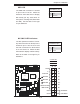
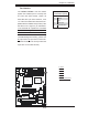
PCI-X 133 MHz
S
UPER PDSM4+
®
Dural Core CPU
LGA 775
KB/MS
COM1
GLAN1
Fan5
North Bridge
LAN
CTRL
JPL1
SCSI
SATA1
Fan4
Buzzer
JLED
IDE
24-Pin ATX PWR
ICH7R
DIMM#1A (Blue)
DIMM#1B (Black)
DIMM#2A (Blue)
DIMM#2B
(Black)
JBT1
South Bridge
JPW2
8-pin PWR
SATA3
Fan2
Battery
JPA1
Fan3
JPA2
PCI-X#1 100MHz
SCSI Channel
FP CTRL
LE3
SATA0
SATA2
JWOR
JWD
SPKR
(Green Slot*PDSM4+)
USB 1,2
VGA
GLAN2
LAN
CTRL
BIOS
SIM 1U Slot
Slot1
Slot2
Slot4
PCI-E x4
Slot5
Slot6
PCI-X 133 MHz
VGA
PXH
JP6
Slot7
PCI-E x8
LE1
LE4
JPF
Fan1
CPU Fan6
PW3
JL1
JPWAKE
Floppy
COM2
PWR I
2
C
JPUSB1
JPR1
SI/O
HW
793
JPL2
USB3
JUSB2
CTRL
JPG1
WOL
Video
Memory
CTLR
JP5
PCI-X#2 100MHz ZCR
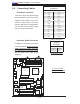
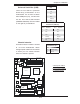
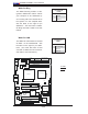
Fan Headers
The PDSM4+/PDSME+ has fi ve chasis/
system fan headers (Fan1 to Fan5) and
one CPU Fan (CPU Fan6). (*Note: all
these fans are 4-pin fans. However, Pins
1-3 of the fan headers are backward com-
patible with the traditional 3-pin fans.) See
the table on the right for pin defi nitions.
(*The onboard fan speeds are controlled
by Thermal Management via BIOS Hard-
ware Monitor in the Advanced Setting
.
Note: Default: Disabled, When using
Thermal Management setting, please use
all 3-pin fans or all 4-pin fans on the moth-
erboard. Please do not use 3-pin fans and
4-pin fans on the same board.)
D
E
DF
C
B
A
4-pin Fan Header
Pin Defi nitions (Fan5-8)
Pin# Defi nition
1 Ground
2 +12V
3 Tachometer
4 PWR Modulation
A. Fan 1
B. Fan 2
C. Fan 3
D. Fan 4
E. Fan 5
F. Fan 6 (CPU Fan)