
Datasheet

2-20
PDSM4+/PDSME+ User's Manual
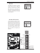
PCI-X 133 MHz
S
UPER PDSM4+
®
Dural Core CPU
LGA 775
KB/MS
COM1
GLAN1
Fan5
North Bridge
LAN
CTRL
JPL1
SCSI
SATA1
Fan4
Buzzer
JLED
IDE
24-Pin ATX PWR
ICH7R
DIMM
#1A (Blue)
DIMM#1B (Black)
DIMM#2A (Blue)
DIMM#2B
(Black)
JBT1
South Bridge
JPW2
8-pin PWR
SATA3
Fan2
Battery
JPA1
Fan3
JPA2
PCI-X#1 100MHz
SCSI Channel
FP CTRL
LE3
SATA0
SATA2
JWOR
JWD
SPKR
(Green Slot*PDSM4+)
USB 1,2
VGA
GLAN2
LAN
CTRL
BIOS
SIM 1U Slot
Slot1
Slot2
Slot4
PCI-E x4
Slot5
Slot6
PCI-X 133 MHz
VGA
PXH
JP6
Slot7
PCI-E x8
LE1
LE4
JPF
Fan1
CPU Fan
6
PW3
JL1
JPWAKE
Floppy
COM2
PWR I
2
C
JPUSB1
JPR1
SI/O
HW
793
JPL2
USB3
JUSB2
CTRL
JPG1
WOL
Video
Memory
CTLR
JP5
PCI-X#2 100MHz ZCR
B
A
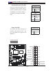
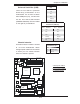
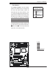
Wake-On-Ring
The Wake-On-Ring header is des-
ignated JWOR.This feature allows
your computer to be awakened by
an incoming call to the modem when
the system is in the suspend state.
See the table on the right for pin
defi nitions. You must have a Wake-
On-Ring card and a cable to use this
feature.
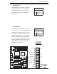
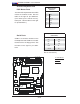
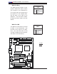
Wake-On-LAN
The Wake-On-LAN header is located
at JWOL on the motherboard. See
the table on the right for pin defi ni-
tions. (You must also have a LAN
card with a Wake-On-LAN connector
and cable to use this feature.)
Wake-On-Ring
Pin Defi nitions
(JWOR)
Pin# Defi nition
1 Ground
2 Wake-up
Wake-On-LAN
Pin Defi nitions
(JWOL)
Pin# Defi nition
1 +5V Standby
2 Ground
3 Wake-up
A. WOR
B. WOL