
Datasheet


Chapter 2: Installation
2-25
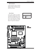
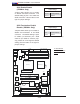
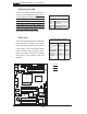
PCI-X 133 MHz
S
UPER PDSM4+
®
Dural Core CPU
LGA 775
KB/MS
COM1
GLAN1
Fan5
North Bridge
LAN
CTRL
JPL1
SCSI
SATA1
Fan4
Buzzer
JLED
IDE
24-Pin ATX PWR
ICH7R
DIMM#1A (Blue)
DIMM#1B (Black)
DIMM#2A (Blue)
DIMM#2B (Black)
JBT1
South Bridge
JPW2
8-pin PWR
SATA3
Fan2
Battery
JPA1
Fan3
JPA2
PCI-X#1 100MHz
SCSI Channel
FP CTRL
LE3
SATA0
SATA2
JWOR
JWD
SPKR
(Green Slot*PDSM4+)
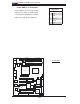
USB 1,2
VGA
GLAN2
LAN
CTRL
BIOS
SIM 1U Slot
Slot1
Slot2
Slot4
PCI-E x4
Slot5
Slot6
PCI-X 133 MHz
VGA
PXH
JP6
Slot7
PCI-E x8
LE1
LE4
JPF
Fan1
CPU Fan6
PW3
JL1
JPWAKE
Floppy
COM2
PWR I
2
C
JPUSB1
JPR1
SI/O
HW
793
JPL2
USB3
JUSB2
CTRL
JPG1
WOL
Video
Memory
CTLR
JP5
PCI-X#2 100MHz ZCR
B
A
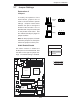
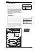
SMBus to PCI/PCI-Exp. Slots
Jumpers JP5, JP6 allow your PCIX/
PCI-E card to be connected to the
System Management Bus
. The default
setting is "Open" to disable the con-
nection. See the table on the right for
jumper settings.
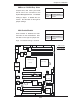
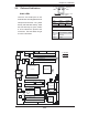
VGA Enable/Disable
JPG1 enables or disables the VGA
Connector on the motherboard. See
the table on the right for jumper set-
tings. The default setting is enabled.
B
SMB to PCI Enable
Pin# Defi nition
Open Disabled (*default)
Closed Enabled
VGA Enable
Pin# Defi nition
Pins 1-2 Enabled (*default)
Pins 2-3 Disabled
A. SMB to PCI
B. VGA Enable