
Datasheet


Chapter 2: Installation
2-27
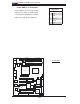
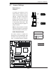
PCI-X 133 MHz
S
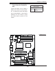
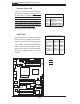
UPER PDSM4+
®
Dural Core CPU
LGA 775
KB/MS
COM1
GLAN1
Fan5
North Bridge
LAN
CTRL
JPL1
SCSI
SATA1
Fan4
Buzzer
JLED
IDE
24-Pin ATX PWR
ICH7R
DIMM#1A (Blue)
DIMM
#1B (Black)
DIMM#2A (Blue)
DIMM#2B (Black)
JBT1
South Bridge
JPW2
8-pin PWR
SATA3
Fan2
Battery
JPA1
Fan3
JPA2
PCI-X#1 100MHz
SCSI Channel
FP CTRL
LE3
SATA0
SATA2
JWOR
JWD
SPKR
(Green Slot*PDSM4+)
USB 1,2
VGA
GLAN2
LAN
CTRL
BIOS
SIM 1U Slot
Slot1
Slot2
Slot4
PCI-E x4
Slot5
Slot6
PCI-X 133 MHz
VGA
PXH
JP6
Slot7
PCI-E x8
LE1
LE4
JPF
Fan1
CPU Fan6
PW3
JL1
JPWAKE
Floppy
COM2
PWR I
2
C
JPUSB1
JPR1
SI/O
HW
793
JPL2
USB3
JUSB2
CTRL
JPG1
WOL
Video
Memory
CTLR
JP5
PCI-X#2 100MHz ZCR
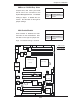
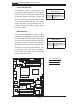
Force-Power-On Enable/Dis-
able
Jumper JPF allows you to enable or
disable the function of Force-Power-
On. If enabled, the power will always
stay on automatically. If this function
disabled, the user needs to press
the power button to power on the
system.
A
Power Force On
Jumper Settings
Pin# Defi nition
Off Normal
On Force On
A. PWR Force On