
Datasheet


2-30
PDSM4+/PDSME+ User's Manual
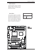
PCI-X 133 MHz
S
UPER PDSM4+
®
Dural Core CPU
LGA 775
KB/MS
COM1
GLAN1
Fan5
North Bridge
LAN
CTRL
JPL1
SCSI
SATA1
Fan4
Buzzer
JLED
IDE
24-Pin ATX PWR
ICH7R
DIMM#1A (Blue)
DIMM#1B (Black)
DIMM#2A (Blue)
DIMM#2B
(Black)
JBT1
South Bridge
JPW2
8-pin PWR
SATA3
Fan2
Battery
JPA1
Fan3
JPA2
PCI-X#1 100MHz
SCSI Channel
FP CTRL
LE3
SATA0
SATA2
JWOR
JWD
SPKR
(Green Slot*PDSM4+)
USB 1,2
VGA
GLAN2
LAN
CTRL
BIOS
SIM 1U Slot
Slot1
Slot2
Slot4
PCI-E x4
Slot5
Slot6
PCI-X 133 MHz
VGA
PXH
JP6
Slot7
PCI-E x8
LE1
LE4
JPF
Fan1
CPU Fan6
PW3
JL1
JPWAKE
Floppy
COM2
PWR I
2
C
JPUSB
1
JPR1
SI/O
HW
793
JPL2
USB3
JUSB2
CTRL
JPG1
WOL
Video
Memory
CTLR
JP5
PCI-X#2 100MHz ZCR
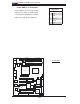
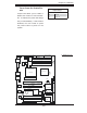
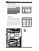
Onboard Power LED
There is an Onboard Power LED (LE1)
located on the motherboard. When LE1 is
off, the system is off. When the green light
is on, the system is on. When the yellow
light is on, the system is off, but the AC
power cable is still connected. Make sure
to disconnect the power cable before re-
moving or installing components. See the
layout below for the LED location.
Onboard PWR LED Indicator (LE1)
LED Color Defi nition
Off System Off
Green System On
Yellow System off, PWR Cable
Connected
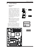
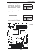
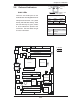
POST LEDs
There are two POST (Power-On Self Test)
LEDs (LE3, LE4) located on the mother-
board. The green LED is LE3; while the
yellow LED is LE4. These LEDs indicate
POST activities during system bootup.
Refer to the table on the right for details.
Also see the layout below for the LED
locations.
A. LE1
B. LE3
C. LE4
A
B
C
POST LED Indicators (LE3/LE4)
LE3 LE4
Green Yellow
POST On On
Memory Initial. Blinking Blinking
PCI Initialization On Blinking
Video Initial. Blinking On
POST Com-
pleted
Off Off