
Datasheet


2-8
PDSMA+ User's Manual
Power Butto
n
OH/Fan Fail LED
1
NIC1 LED
Reset Button
2
HDD LED
Power LED
Reset
PWR
Vcc
Vcc
Vcc
Vcc
Ground
Ground
1920
Vcc
X
Ground
NMI
X
Vcc
X
NIC2 LED
S
UPER PDSMA+
®
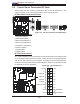
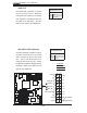
B. Front Control Panel
JF1 contains header pins for various buttons and indicators that are normally located
on a control panel at the front of the chassis. These connectors are designed specifi -
cally for use with Supermicro server chassis. See Figure 2-4 for the descriptions of
the various control panel buttons and LED indicators. Refer to the following section
for descriptions and pin defi nitions.
Figure 2-4. JF1 Header Pins
S
UPER PDSMA+
®
Figure 2-3. I/O Port Locations and Defi nitions
1
2
3
4
5
6
7
8
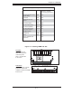
Back Panel Connectors
1. Keyboard (Purple)
2. PS/2 Mouse (Green)
3. Back Panel USB Port 1
4. Back Panel USB Port 2
5. COM Port 1 (Turquoise)
6. VGA Port (Blue)
7. Gigabit LAN 1
8. Gigabit LAN 2
2-5 Control Panel Connectors/IO Ports
The I/O ports are color coded in conformance with the PC 99 specifi cation. See
Figure 2-3 below for the colors and locations of the various I/O ports.
A. Back Panel Connectors/IO Ports