
Datasheet


2-14
PDSMA+ User's Manual
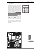
PCI 32-bit 33 MHz
S
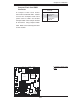
UPER PDSMA+
®
CPU
LGA 775
KB/MS
COM1
JLAN1
North Bridge
JPL1
JL1
JLED
24-Pin ATX PWR
ICH7R
South Bridge
8-pin PWR
Battery
J9
FP CTRL
USB 1/2
VGA
JLAN2
LAN1
CTRL
S I/O
Printer
JPL2
Floppy
DIMM 2B
PCI-X 64-bit 133 MHz
BIOS
PXH-V
Primary IDE
JWOR
LE1
JBT1
USB3/4
USB5/6
JP3
JPF
JWD
WOL
Fan3
DIMM 1B
DIMM 2A
DIMM 1A
VGA
CTRL
LE3
LE4
*Compact Flash only
COM2
PCI 32-bit 33 MHz
JI2C1
JI2C2
JPG1
LAN2
CTRL
IPMI 2.0
SATA0
SATA1
SATA2
SATA3
Fan1
Fan4
Fan6
Fan2
Fan5
PCI 32-bit 33 MHz
PCI 32-bit 33 MHz
PCI 32-bit 33 MHz
JWF1
SPKR
PCI-Exp. x8
Intel 3000
JPR1
PW3
PW4
(CPUFan)
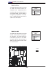
Chassis Intrusion
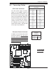
A Chassis Intrusion header is located
at JL1. Attach the appropriate cable
to inform you of a chassis intrusion.
Chassis Intrusion
Pin Defi nitions (JL1)
Pin# Defi nition
1 Intrusion Input
2 Ground
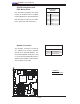
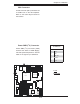
A
B
A. COM1
B. COM2
C. Chassis Intrusion
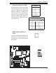
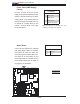
Serial Ports
Two serial headers: COM1 (J31),
COM2 are included on the mother-
board. COM1 (J31) is a port located
next to VGA port. See the table on the
right for pin defi nitions.
Serial Port Pin Defi nitions
(COM1/COM2)
Pin # Defi nition Pin # Defi nition
1 CD 6 DSR
2RD 7RTS
3 TD 8 CTS
4DTR 9RI
5 Ground 10 NC
Note: Pin 10 is included on the header but not on
the port. NC indicates no connection.
C