
Datasheet


2-20
PDSMA+ User's Manual
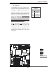
PCI 32-bit 33 MHz
S
UPER PDSMA+
®
CPU
LGA 775
KB/MS
COM1
JLAN1
North Bridge
JPL1
JL1
JLED
24-Pin ATX PWR
ICH7R
South Bridge
8-pin PWR
Battery
J9
FP CTRL
USB 1/2
VGA
JLAN2
LAN1
CTRL
S I/O
Printer
JPL2
Floppy
DIMM 2B
PCI-X 64-bit 133 MHz
BIOS
PXH-V
Primary IDE
JWOR
LE1
JBT1
USB3/4
USB5/6
JP3
JPF
JWD
WOL
Fan3
DIMM 1B
DIMM 2A
DIMM 1A
VGA
CTRL
LE3
LE4
*Compact Flash only
COM2
PCI 32-bit 33 MHz
JI2C1
JI2C2
JPG1
LAN2
CTRL
IPMI 2.0
SATA0
SATA1
SATA2
SATA3
Fan1
Fan4
Fan6
Fan2
Fan5
PCI 32-bit 33 MHz
PCI 32-bit 33 MHz
PCI 32-bit 33 MHz
JWF1
SPKR
PCI-Exp. x8
Intel 3000
JPR1
PW3
PW4
(CPUFan)
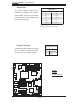
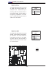
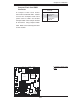
Power Fault (PWR Supply
Failure)
Connect a cable from your power
supply to the Power Fail (PSF) header
(PW3) to provide a warning of power
supply failure. This warning signal is
passed through the PWR_LED pin
to indicate of a power failure on the
chassis. See the table on the right
for pin defi nitions.
Note: This feature is only available when using
Supermicro redundant power supplies.
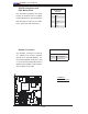
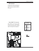
Alarm Reset
If three power supplies are installed
and Alarm Reset (JPR1) is enabled,
the system will notify you when any
of the three power modules fails. Con-
nect JPR1 to a micro-switch to turn
off the alarm that is activated when a
power module fails. See the table on
the right for pin defi nitions.
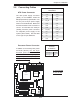
PWR Supply Fail LED
Pin Defi nitions
Pin# Defi nition
1 PWR 1: Fail
2 PWR 2: Fail
3 PWR 3: Fail
4 Signal: Alarm Reset
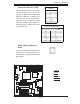
Alarm Reset
Pin Setting Defi nition
Pin 1 Ground
Pin 2 +5V
A
B
A. Power Fault
B. Alarm Reset