
Datasheet


Chapter 2: Installation
2-27
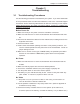
PCI 32-bit 33 MHz
S
UPER PDSMA+
®
CPU
LGA 775
KB/MS
COM1
JLAN1
North Bridge
JPL1
JL1
JLED
24-Pin ATX PWR
ICH7R
South Bridge
8-pin PWR
Battery
J9
FP CTRL
USB 1/2
VGA
JLAN2
LAN1
CTRL
S I/O
Printer
JPL2
Floppy
DIMM 2B
PCI-X 64-bit 133 MHz
BIOS
PXH-V
Primary IDE
JWOR
LE1
JBT1
USB3/4
USB5/6
JP3
JPF
JWD
WOL
Fan3
DIMM 1B
DIMM 2A
DIMM 1A
VGA
CTRL
LE3
LE4
*Compact Flash only
COM2
PCI 32-bit 33 MHz
JI2C1
JI2C2
JPG1
LAN2
CTRL
IPMI 2.0
SATA0
SATA1
SATA2
SATA3
Fan1
Fan4
Fan6
Fan2
Fan5
PCI 32-bit 33 MHz
PCI 32-bit 33 MHz
PCI 32-bit 33 MHz
JWF1
SPKR
PCI-Exp. x8
Intel 3000
JPR1
PW3
PW4
(CPUFan)
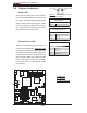
B
A. LE3
B. LE4
A
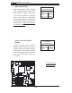
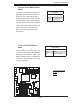
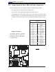
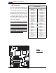
BIOS POST Code LEDs
There are two POST (Power-On Self
Test) Code LEDs (LE3, LE4) located on
the motherboard. The green LED is LE3,
and the yellow LED is LE4. These LEDs
indicate POST activities during system
bootup. Refer to the table on the right for
details. Also see the layout below for the
LED locations.
POST LED Indicators (LE3/LE4)
LE3 LE4
Green Yellow
POST On On
Memory Initial. Blinking Blinking
PCI Initialization On Blinking
Video Initial. Blinking On
POST Com-
pleted
Off Off