
Datasheet


A-1
Appendix A: BIOS POST Messages
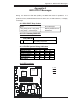
PCI 32 Bit/33 MHz
S
UPER PDSMi
REV 1.0
®
Pentium Dual
Core CPU
LGA 775
KB/MS
COM1
GLAN1
E7230
(North Bridge)
LAN
CTRL
JPL1
Fan4
Buzzer
JLED
24-Pin ATX PWR
ICH7R
JF1
(South Bridge)
J31
J28
Fan6/CPU Fan
8-pin PWR
Battery
J9
FP CTRL
USB 1/2
J15
VGA
JG1
GLAN2
LAN
CTRL
S I/O
COM2
JPL2
Printer
Floppy
Slot1
SXB -E1 PCI-Ex8
DIMM 2B
PCI-X 133 MHz
BIOS
PXH-V
IPMI
Mukilteo
JPW1
J30
J27
IDEJ4
J3
IDE (Primary)
JWOR
LE1
JBT1
USB3/4 USB5/6
JWF1
JPG1
JPF
JWD
WOL
Fan3
Fan2
DIMM 1B
DIMM 2A
DIMM 1A
DIMM 1
DIMM 2
DIMM 3
DIMM 4
Fan1
JPW2
VGA
CTRL
Slot6
LE3
LE4
SATA0
SATA1
SATA2
SATA3
(*Compact Flash Card only)
JL1
JP3
JI
2
C1
JI
2
C2
Fan5
During the Power-On Self-Test (POST), the BIOS will check for problems. If a
problem is found, the BIOS will activate an alarm, turn on LED indicators, or display
a message.
A-1 BIOS POST Beep Codes
Beeps Error Messages
1 long beep-pause-1 long beep Memory Module Errors
1 long beep + 2 short beeps VGA Errors
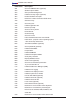
A-2 LE1: Standby PWR LED
A-3 LE3/LE4 System Debug Indicators
A-4 LED Locations
State LE3 Indicator LE4 Indicator
PWR-ON to POST
Green On Yellow On
ECC Memory Testing
Green Flash Yellow Flash
PCI Bus Initializing
Green On Yellow Flash
VGA Initializing
Green Flash Yellow On
System Normal
(After POST)
Off N/A Off N/A
LE1:
5V Standby PWR LED
Action
On
Standby PWR On Turn off the PWR supply before removing
or installing components
A. LE1
B. LE3
C. LE4
A
B
C
Appendix A
BIOS POST Messages