
User's Manual (1.0d)

B-4
SC113 Chassis Manual
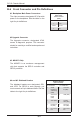
#4 and #5. Sideband Headers
The sideband headers are designated JP51
and JP52. For SES-2 to work properly, you
must connect an 8-pin sideband cable. See the
table to the right for pin denitions.
Sideband Headers
(JP51 and JP52)
Pin # Denition Pin # Denition
2 SDIN/
Backplane
Addressing
(SB5)
1 Controller
ID (SB6)
4 SDOUT/I
2
C
Reset
(SB4)
3 GND (SB2)
6 GND (SB3) 5 SLOAD/
SDA (SB1)
8 Backplane
ID (SB7)
7 SCLOCK/
SCL (SB0)
10 No Connec-
tion
9 No Connec-
tion
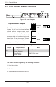
#3. MG9072 Chip
The MG9072 is an enclosure management
chip that supports the SES-2 controller and
SES-2 protocols.
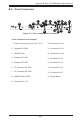
B-6 Front Connector and Pin Denitions
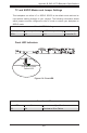
#2 Upgrade Connector
The Upgrade connector, designated JP46,
serves a diagnostic purpose. This connector
should be used by a certied and experienced
technician.
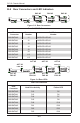
Backplane
Main Power
4-Pin Connector
(JP10)
Pin# Denition
1
+12V
2 and 3
Ground
4 +5V
#1. Backplane Main Power Connectors
The 4-pin connectors, designated JP10 provide
power to the backplane. See the table on the
right for pin denitions.