
User's Manual (1.0b)


SC216 Chassis Manual
F-2
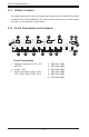
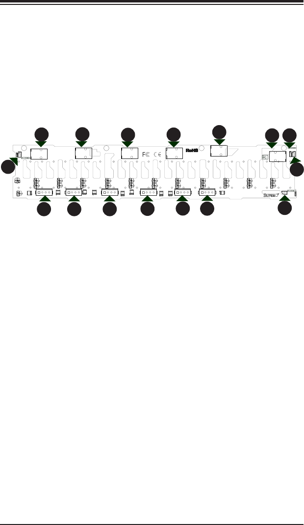
Front Connectors
1. Upgrade Connectors: JP70, JP71
and JP72
2. Jumper: JP35
3. Power Connectors (4-pin): JP10,
JP13, JP46, JP48 JP109, JP110
4. SAS IN#1 JSM1
5. SAS IN#2 JSM2
6. SAS IN#3 JSM3
7. SAS IN#4 JSM4
8. SAS IN#5 JSM5
9. SAS IN#6 JSM6
1 4
1 4
1 4
1
4
1 4
1
4
1
3
1 2
5
6
1
2
5
6
1 2
5 6
+
++
+
+
+
++
+
+
+
+
++
++
+
+
+
++
++
3
2
1
1
2
3
BPN-SAS3-216A
SAS IN#1
SAS IN#2
SAS IN#3SAS IN#4SAS IN#5
SAS IN#6
JP13
JP10
JP109
JP110
JP46
JP48
Q88
Q90
Q86
Q85
Q83
Q82
Q87
Q84
Q89
JP35
JP72
JP71
JP70
JSM6
C9
C8
C7
C65
C60
C6
C55 C54 C53
C52
C51
C50
C5
C49
C48
C47 C44
C34
C31
C30
C13 C12
C11
C10
MH2MH3 MH4MH1
ATMEL RST
JP35
1-2:RST
2-3:NO RST
UPwRADE#1JP70:
UPGRADE#3
JP72:
UPGRADE#2JP71:
1
2
1
3
4
5
67
1
3
3
333
89
F-3 A Note to Users
All images and layouts in this user's guide are based upon the latest PCB revision
available at the time of publishing. The card you have received may not look exactly
the same as the graphics in this manual.
F-4 Front Connectors and Jumpers