
User's Manual (1.0b)


F-3
Appendix F SAS3-216A Backplane Specications
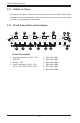
F-5 FrontConnectorandPinDenitions
1. Upgrade Connectors
The upgrade connectors are used for manufac-
turer diagnostic purposes only.
Backplane
Main Power
4-Pin Connector
Pin# Denition
1
+12V
2 and 3 Ground
4 +5V
3. Backplane Main Power Connectors
The 4-pin connectors, designated JP10, JP13,
JP46, JP48, JP109 and JP110 provide power
to the backplane. See the table on the right for
pin denitions.
4. - 9. SAS IN Ports (Sideband included)
The SAS ports are used to connect the SAS
drive cables. The six SAS IN ports are des-
ignated #JSM1 - #JSM6. Each port is also
compatible with SATA drives.
SidebandDenitions
(JSM1 - JSM6)
Pin # Denition Pin # Denition
A0 SB0 C1 SB4
B2 SB1 D1 SB5
C2 SB2 D2 SB6
B1 SB3 A1 SB7
F-6 Jumpers
Explanation of Jumpers
To modify the operation of the backplane,
jumpers can be used to choose between
optional settings. Jumpers create shorts
between two pins to change the func-
tion of the connector. Pin 1 is identied
with a square solder pad on the printed
circuit board. Note: On two pin jumpers,
"Closed" means the jumper is on and
"Open" means the jumper is off the pins.
2. Jumper
Connector
Pins
Jumper
Setting
3 2 1
3 2 1
Jumper Settings
Jumper Jumper Settings Notes
JP35
Pins 1-2 Reset
Pins 2-3 Normal (default)
ATMEL chip reset