
User's Manual (1.0b)


C-4
SC216 Chassis Manual
C-6 FrontConnectorsandPinDenitions
1. Upgrade Connectors
The upgrade connectors are designated JP69,
JP78 and JP115 are used for manufacturer's
diagnostic purposes only.
2. - 7. I
2
C Connectors
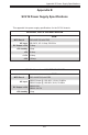
The I
2
C Connectors, designated JP37, JP95,
JP52, JP96, JP115 and JP116 are used to
monitor HDD activity and status. See the table
on the right for pin denitions.
I
2
C Connector
PinDenitions
Pin# Denition
1 Data
2 Ground
3 Clock
4 No Connection
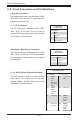
Backplane
Main Power
4-Pin Connector
Pin# Denition
1
+12V
2 and 3 Ground
4 +5V
8. Backplane Main Power Connectors
The 4-pin connectors, designated JP10, JP13,
JP46, JP48, JP109 and JP110 provide power
to the backplane. See the table on the right for
pin denitions.
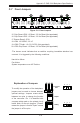
9. - 14. SAS IN Ports (Sideband included)
The SAS ports are used to connect the SAS
drive cables. The six SAS IN ports are des-
ignated #JSM1 - #JSM6. Each port is also
compatible with SATA drives.
SidebandDenitions
Pin # Denition Pin # Denition
A11 SGPIO:
SDIN
I
2
C:
Backplane
Addressing
(SB5)
B11 Controller ID
(SB6)
A12 SGPIO:
SDOUT
I
2
C: Reset
(SB4)
B10 GND (SB2)
A9 GND (SB3) B9 SGPIO:
SLOAD
I
2
C:SDA
(SB1)
A8 Backplane
ID (SB7)
B8 SGPIO:
SCLOCK
I
2
C:SCL
(SB0)