SUPER ® SC510 Chassis Series SC510-200B SC510L-200B SC510T-200B SC510-203B SC510T-203B USER’S MANUAL 1.
The information in this User’s Manual has been carefully reviewed and is believed to be accurate. The vendor assumes no responsibility for any inaccuracies that may be contained in this document, makes no commitment to update or to keep current the information in this manual, or to notify any person or organization of the updates. Please Note: For the most up-to-date version of this manual, please see our web site at www.supermicro.com. Super Micro Computer, Inc.
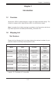
Preface Preface About This Manual This manual is written for professional system integrators and PC technicians. It provides information for the installation and use of the SC510 chassis. Installation and maintenance should be performed by experienced technicians only. Supermicro’s mini-sized SC510 1U chassis features a depth of only 11.3" with an advanced airflow and thermal design for client nodes, firewall applications, mail servers, Web servers and other server applications.
SC510 Chassis Manual Manual Organization Chapter 1 Introduction The first chapter provides an overview of the main components and features of the SC510 chassis. This chapter also includes contact information. Chapter 2 Warning Statements for AC Systems This section lists warnings, precautions, and system safety. It is recommended that you thoroughly familiarize yourself with this chassis safety precautions.
Preface Contents Chapter 1 Introduction 1-1 Overview.......................................................................................................... 1-1 1-2 Shipping List..................................................................................................... 1-1 Part Numbers................................................................................................... 1-1 1-3 Where to get Replacement Components.........................................................
SC510 Chassis Manual 4-4 Drive Carrier LEDs........................................................................................... 4-4 4-5 Power Supply LEDs......................................................................................... 4-4 Chapter 5 Chassis Setup and Maintenance 5-1 Overview.......................................................................................................... 5-1 5-2 Removing Power from the System......................................................
Chapter 1: Introduction Chapter 1 Introduction 1-1 Overview Supermicro’s SC510 chassis features a unique and highly-optimized design. The chassis is equipped with a high-efficiency 80%+ low-noise power supply. Note: A complete list of safety warnings is provided on the Supermicro web site at http://www.supermicro.com/about/policies/safety_information.cfm.
SC510 Chassis Manual 1-3 Where to get Replacement Components Though not frequently, you may need replacement parts for your system. To ensure the highest level of professional service and technical support, we strongly recommend purchasing exclusively from our Supermicro Authorized Distributors/ System Integrators/Resellers. A list of Supermicro Authorized Distributors/System Integrators/Reseller can be found at: http://www.supermicro.com. Click the Where to Buy link.
Chapter 1: Introduction 1-4 Contacting Supermicro Headquarters Address: Super Micro Computer, Inc. 980 Rock Ave. San Jose, CA 95131 U.S.A. Tel: +1 (408) 503-8000 Fax: +1 (408) 503-8008 Email: marketing@supermicro.com (General Information) support@supermicro.com (Technical Support) Web Site: www.supermicro.com Europe Address: Super Micro Computer B.V. Het Sterrenbeeld 28, 5215 ML 's-Hertogenbosch, The Netherlands Tel: +31 (0) 73-6400390 Fax: +31 (0) 73-6416525 Email: sales@supermicro.
SC510 Chassis Manual Notes 1-4
Chapter 2: Warning Statements for AC Systems Chapter 2 Standardized Warning Statements for AC Systems 2-1 About Standardized Warning Statements The following statements are industry standard warnings, provided to warn the user of situations which have the potential for bodily injury. Should you have questions or experience difficulty, contact Supermicro's Technical Support department for assistance. Only certified technicians should attempt to install or configure components.
SC510 User's Manual Warnung WICHTIGE SICHERHEITSHINWEISE Dieses Warnsymbol bedeutet Gefahr. Sie befinden sich in einer Situation, die zu Verletzungen führen kann. Machen Sie sich vor der Arbeit mit Geräten mit den Gefahren elektrischer Schaltungen und den üblichen Verfahren zur Vorbeugung vor Unfällen vertraut. Suchen Sie mit der am Ende jeder Warnung angegebenen Anweisungsnummer nach der jeweiligen Übersetzung in den übersetzten Sicherheitshinweisen, die zusammen mit diesem Gerät ausgeliefert wurden.
Warning Statements for AC Systems 안전을 위한 주의사항 경고! 이 경고 기호는 위험이 있음을 알려 줍니다. 작업자의 신체에 부상을 야기 할 수 있는 상태에 있게 됩니다. 모든 장비에 대한 작업을 수행하기 전에 전기회로와 관련된 위험요소들을 확인하시고 사전에 사고를 방지할 수 있도록 표준 작업절차를 준수해 주시기 바랍니다. 해당 번역문을 찾기 위해 각 경고의 마지막 부분에 제공된 경고문 번호를 참조하십시오 BELANGRIJKE VEILIGHEIDSINSTRUCTIES Dit waarschuwings symbool betekent gevaar. U verkeert in een situatie die lichamelijk letsel kan veroorzaken.
SC510 User's Manual Installation Instructions Warning! Read the installation instructions before connecting the system to the power source. 設置手順書 システムを電源に接続する前に、設置手順書をお読み下さい。 警告 将此系统连接电源前,请先阅读安装说明。 警告 將系統與電源連接前,請先閱讀安裝說明。 Warnung Vor dem Anschließen des Systems an die Stromquelle die Installationsanweisungen lesen. ¡Advertencia! Lea las instrucciones de instalación antes de conectar el sistema a la red de alimentación.
Chapter 2: Warning Statements for AC Systems Circuit Breaker Warning! This product relies on the building's installation for short-circuit (overcurrent) protection. Ensure that the protective device is rated not greater than: 250 V, 20 A.
SC510 User's Manual 경고! 이 제품은 전원의 단락(과전류)방지에 대해서 전적으로 건물의 관련 설비에 의존합니다. 보호장치의 정격이 반드시 250V(볼트), 20A(암페어)를 초과하지 않도록 해야 합니다. Waarschuwing Dit product is afhankelijk van de kortsluitbeveiliging (overspanning) van uw electrische installatie. Controleer of het beveiligde aparaat niet groter gedimensioneerd is dan 220V, 20A.
Chapter 2: Warning Statements for AC Systems ¡Advertencia! El sistema debe ser disconnected de todas las fuentes de energía y del cable eléctrico quitado de los módulos de fuente de alimentación antes de tener acceso el interior del chasis para instalar o para quitar componentes de sistema. Attention Le système doit être débranché de toutes les sources de puissance ainsi que de son cordon d'alimentation secteur avant d'accéder à l'intérieur du chassis pour installer ou enlever des composants de systéme.
SC510 User's Manual Equipment Installation Warning! Only trained and qualified personnel should be allowed to install, replace, or service this equipment. 機器の設置 トレーニングを受け認定された人だけがこの装置の設置、交換、 またはサービスを許可 されています。 警告 只有经过培训且具有资格的人员才能进行此设备的安装、更换和维修。 警告 只有經過受訓且具資格人員才可安裝、更換與維修此設備。 Warnung Das Installieren, Ersetzen oder Bedienen dieser Ausrüstung sollte nur geschultem, qualifiziertem Personal gestattet werden. ¡Advertencia! Solamente el personal calificado debe instalar, reemplazar o utilizar este equipo.
Chapter 2: Warning Statements for AC Systems Waarschuwing Deze apparatuur mag alleen worden geïnstalleerd, vervangen of hersteld door geschoold en gekwalificeerd personeel. Restricted Area Warning! This unit is intended for installation in restricted access areas. A restricted access area can be accessed only through the use of a special tool, lock and key, or other means of security. (This warning does not apply to workstations).
SC510 User's Manual 경고! 이 장치는 접근이 제한된 구역에 설치하도록 되어있습니다. 특수도구, 잠금 장치 및 키, 또는 기타 보안 수단을 통해서만 접근 제한 구역에 들어갈 수 있습니다. Waarschuwing Dit apparaat is bedoeld voor installatie in gebieden met een beperkte toegang. Toegang tot dergelijke gebieden kunnen alleen verkregen worden door gebruik te maken van speciaal gereedschap, slot en sleutel of andere veiligheidsmaatregelen. Battery Handling Warning! There is the danger of explosion if the battery is replaced incorrectly.
Chapter 2: Warning Statements for AC Systems Warnung Bei Einsetzen einer falschen Batterie besteht Explosionsgefahr. Ersetzen Sie die Batterie nur durch den gleichen oder vom Hersteller empfohlenen Batterietyp. Entsorgen Sie die benutzten Batterien nach den Anweisungen des Herstellers. Attention Danger d'explosion si la pile n'est pas remplacée correctement. Ne la remplacer que par une pile de type semblable ou équivalent, recommandée par le fabricant.
SC510 User's Manual Redundant Power Supplies Warning! This unit might have more than one power supply connection. All connections must be removed to de-energize the unit. 冗長電源装置 このユニットは複数の電源装置が接続されている場合があります。 ユニットの電源を切るためには、すべての接続を取り外さなければなりません。 警告 此部件连接的电源可能不止一个,必须将所有电源断开才能停止给该部件供电。 警告 此裝置連接的電源可能不只一個,必須切斷所有電源才能停止對該裝置的供電。 Warnung Dieses Gerät kann mehr als eine Stromzufuhr haben. Um sicherzustellen, dass der Einheit kein trom zugeführt wird, müssen alle Verbindungen entfernt werden.
Chapter 2: Warning Statements for AC Systems 경고! 이 장치에는 한 개 이상의 전원 공급 단자가 연결되어 있을 수 있습니다. 이 장치에 전원을 차단하기 위해서는 모든 연결 단자를 제거해야만 합니다. Waarschuwing Deze eenheid kan meer dan één stroomtoevoeraansluiting bevatten. Alle aansluitingen dienen verwijderd te worden om het apparaat stroomloos te maken. Backplane Voltage Warning! Hazardous voltage or energy is present on the backplane when the system is operating. Use caution when servicing.
SC510 User's Manual 경고! 시스템이 동작 중일 때 후면판 (Backplane)에는 위험한 전압이나 에너지가 발생 합니다. 서비스 작업 시 주의하십시오. Waarschuwing Een gevaarlijke spanning of energie is aanwezig op de backplane wanneer het systeem in gebruik is. Voorzichtigheid is geboden tijdens het onderhoud. Comply with Local and National Electrical Codes Warning! Installation of the equipment must comply with local and national electrical codes.
Chapter 2: Warning Statements for AC Systems Attention L'équipement doit être installé conformément aux normes électriques nationales et locales. 경고! 현 지역 및 국가의 전기 규정에 따라 장비를 설치해야 합니다. Waarschuwing Bij installatie van de apparatuur moet worden voldaan aan de lokale en nationale elektriciteitsvoorschriften. Product Disposal Warning! Ultimate disposal of this product should be handled according to all national laws and regulations.
SC510 User's Manual ¡Advertencia! Al deshacerse por completo de este producto debe seguir todas las leyes y reglamentos nacionales. Attention La mise au rebut ou le recyclage de ce produit sont généralement soumis à des lois et/ou directives de respect de l'environnement. Renseignez-vous auprès de l'organisme compétent. 경고! 이 제품은 해당 국가의 관련 법규 및 규정에 따라 폐기되어야 합니다. Waarschuwing De uiteindelijke verwijdering van dit product dient te geschieden in overeenstemming met alle nationale wetten en reglementen.
Chapter 2: Warning Statements for AC Systems 警告 當您從機架移除風扇裝置,風扇可能仍在轉動。小心不要將手指、螺絲起子和其他 物品太靠近風扇。 Warnung Die Lüfter drehen sich u. U. noch, wenn die Lüfterbaugruppe aus dem Chassis genommen wird. Halten Sie Finger, Schraubendreher und andere Gegenstände von den Öffnungen des Lüftergehäuses entfernt. ¡Advertencia! Los ventiladores podran dar vuelta cuando usted quite ell montaje del ventilador del chasis.
SC510 User's Manual Power Cable and AC Adapter Warning! When installing the product, use the provided or designated connection cables, power cables and AC adaptors. Using any other cables and adaptors could cause a malfunction or a fire. Electrical Appliance and Material Safety Law prohibits the use of UL or CSA -certified cables (that have UL/CSA shown on the code) for any other electrical devices than products designated by Supermicro only.
Chapter 2: Warning Statements for AC Systems Attention Lors de l'installation du produit, utilisez les bables de connection fournis ou désigné. L'utilisation d'autres cables et adaptateurs peut provoquer un dysfonctionnement ou un incendie. Appareils électroménagers et de loi sur la sécurité Matériel interdit l'utilisation de UL ou CSA câbles certifiés qui ont UL ou CSA indiqué sur le code pour tous les autres appareils électriques que les produits désignés par Supermicro seulement.
SC510 User's Manual Notes 2-20
Chapter 3: Chassis Components Chapter 3 Chassis Components 3-1 Overview This chapter describes the most common components included with your chassis. Some components listed may not be included or compatible with your particular chassis model. 3-2 Components For the latest shipping lists, visit our Web site at: http://www.supermicro.com. Drives The SC510 or SC510L chassis supports one fixed 3.5" hard drive or up to four fixed 2.5" hard drives. The SC510T chassis supports two hot-swappable 2.
SC510 Chassis Manual Air Shroud Air shrouds are shields, usually plastic, that funnel air directly to where it is needed. Always use the air shroud included with your chassis. Expansion Card The chassis supports one expansion card, depending on the hard drive configuration. See the table in Chapter 1 for details. Control Panel The front control panel includes a power switch, reset button, and five LED status indicators.
Chapter 4: System Interface Chapter 4 System Interface 4-1 Overview The chassis includes: • • • A control panel on the front that houses power buttons and status monitoring lights Status lights on externally accessable hard drives (SC510T models only) Status lights for the power supply visible from the back of the chassis These elements are described in this chapter with possible responses. Figure 4-1.
SC510 Chassis Manual 4-2 Control Panel Buttons The chassis includes two push-buttons that control power to the system. Reset: The reset button is used to reboot the system. Power: The main power switch is used to apply or remove power from the power supply to the server system. Turning off system power with this button removes the main power but keeps standby power supplied to the system. Therefore, you must unplug system before servicing.
Chapter 4: System Interface NIC1: Indicates network activity on GLAN1 when flashing. HDD: Indicates IDE channel activity on the hard drive when flashing. Power: Indicates power is being supplied to the system power supply units. This LED should normally be illuminated when the system is operating. Overheating There are several possible responses if the system overheats. Overheat Temperature Setting Some backplanes allow the overheat temperature to be set at 45, 50, or 55 by changing a jumper setting.
SC510 Chassis Manual 4-4 Drive Carrier LEDs The SC510T series chassis includes externally accessable SAS/SATA drives. Each drive carrier displays two status LEDs on the front of the carrier. • • 4-5 Green: When illuminated, this LED indicates drive activity. It blinks on and off when that particular drive is being accessed This function is controlled by the backplane. Red: When illuminated, this LED indicates a drive failure. You should be notified by your system management software.
Chapter 5: Chassis Setup and Maintenance Chapter 5 Chassis Setup and Maintenance 5-1 Overview This chapter covers the steps required to install components and perform maintenance on the chassis. The only tool you will need to install components and perform maintenance is a Phillips screwdriver. Review the warnings and precautions listed in the manual before setting up or servicing this chassis. These include information in Chapter 2 and the warning/ precautions listed in the setup instructions.
SC510 Chassis Manual 5-3 A Removing the Chassis Cover B C D E F 1 2 G H I K J R E V I S I -×O qN S / DESCRIPTION ±Ô-z REV ª©¥» LOCA ¦ 1 1 RANGE TOLERANCE ½ d³ò ¤½®t X.xx ± 0.10 X.x ± 0.25 X ± 1.00 ²Ä¤T¨¤ª k THE 3RD PROJECTION A BLEC M MODEL NO./ ¾÷«¬ : SC510 ¤j˚T¬ì§ÞªÑ¥÷¦³--¤½¥ q Ablecom Technology Inc. MATERIAL §÷½è / : * DATE / ¤é´Á: SHO 06-Nov-07 FINISHªí-±³ / B¸Ì: DESIGN ³/]-p : UNIT ³æ¦ì / : APPROVED ¼ / f®Ö : See Note. SHO MM Figure 5-1.
Chapter 5: Chassis Setup and Maintenance 5-4 Installing the Hard Drives Installing 3.5" Fixed Hard Drives 1 2 3 4 5 6 7 8 Figure 5-2. Installing the 3.5" Hard Drive Installing a Fixed 3.5" Hard Drive The 3.5" hard drive screws directly into the chassis. 1. Power down the system and remove the power cord from the rear of the power supply as described in Section 5-2. and remove the chassis cover. 2. Place the 3.5" hard drive in the chassis as illustrated above. 3.
B C D SC510 Chassis Manual E F G H I J K Installing 2.5" Fixed Hard Drives A B C D E F G H 1 1 2 3 4 2 5 6 7 8 Figure 5-3. Installing the 2.5" Hard Drives Installing a Fixed 2.5" Hard Drive The 2.5" hard drives (1) must be installed in their brackets (2) before they are screwed into the chassis. RANGE TOLER ½ d³ò ¤ X.xx ± 0 X.x ± 0 X 1. Power down the system and remove the power cord from the rear of the power supply as described in Section 5-2.
Chapter 5: Chassis Setup and Maintenance 5-5 Installing the Motherboard Figure 5-4. Chassis Standoffs Permanent and Optional Standoffs Standoffs prevent short circuits by securing space between the motherboard and the chassis surface. The SC510 chassis includes permanent standoffs in locations used by most motherboards. These standoffs accept the rounded Phillips head screws included in the SC510 accessories packaging.
SC510 Chassis Manual Installing the Motherboard 1. Review the documentation that came with your motherboard. Become familiar with component placement, requirements, precautions, and cable connections. 2. Open the chassis cover. 3. Compare the mounting holes in the chassis to those in the motherboard. Add or remove standoffs as needed. a. Place a hexagonal standoff screw through the bottom the chassis. b. Secure the screw with the hexagon nut (rounded side up). 4.
Chapter 5: Chassis Setup and Maintenance 5-6 A Expansion Card Setup The chassis includes an I/O slot for an optional expansion card, depending on the B C D E F G H I J K hard drive configuration (see Chapter 1). A riser card is required. For further information on expansion cards and risers cards, refer to www.supermicro.com 1 L R E V I S SI / -×O qN REV ª©¥» DESCRIPTION ±Ô-z M SC510 ¤j˚T¬ì§ÞªÑ¥÷¦³--¤½¥ q LOCATIO ¦ì¸ m 2 3 4 5 Expansion Card Clip 6 Figure 5-5.
SC510 Chassis Manual 5. Insert the assembled expansion card and riser card into the expansion slot inside the chassis, carefully aligning the plate of the expansion card with the openings in the back of the chassis. A 6. Replace the expansion card clip and screw it onto the chassis to hold the expansion card in place. B C D E F G H I J K L M R E V I S SI / -×O qN REV ª©¥» DESCRIPTION ±Ô-z M SC510 ¤j˚T¬ì§ÞªÑ¥÷¦³--¤½¥ q LOCATION ¦ì¸ m DRAWN -קïªÌ DATE ¤é´Á 1 2 3 4 5 6 Figure 5-7.
Chapter 5: Chassis Setup and Maintenance 5-7 Installing a Heatsink If you elect to buy a heatsink to help cool the processor, use this procedure. 1. Power down the system as described in Section 5-2 and remove the cover. 2. Disconnect the wiring to the motherboard. 3. Remove the screws securing the motherboard to the chassis and lift it up and out of the chassis. 4. Align the holes of the heatsink, and use the mounting screws to attach the heatsink to the motherboard. 5.
SC510 Chassis Manual 5-8 Installing the Air Shroud 1 Figure 5-9. Air Shroud for SC510 Chassis Air shrouds concentrate airflow to maximize fan efficiency. The SC510 chassis air shroud does not require screws to install. Place the air shroud in the chassis. The air shroud fits behind the fan closest to the power supply. Use the clip on the fan housing to hold the air shroud in place.
Chapter 5: Chassis Setup and Maintenance Checking the Server Airflow • • • • Make sure there are no objects to obstruct airflow in and out of the server. Use only recommended server parts. Make sure no wires or foreign objects obstruct airflow through the chassis. Pull all excess cabling out of the airflow path, or use shorter cables. The control panel LEDs inform you of system status. See “Chapter 3: System Interface” for details on the LEDs and the control panel buttons.
SC510 Chassis Manual 5-9 D System Fans Installing Fans for the SC510-200B/203B or SC510L-200B E F G H Two heavy-duty fans within a single fan housing provide cooling for the chassis. These fans circulate air through the chassis as a means of lowering the chassis internal temperature. 1. If necessary, open the chassis while the power is running to determine which fan has failed (Never run the server for an extended period of time with the chassis open). 2.
REV 版本 DESCRIPTION 敘述 LOCATION 位置 DRAWN 修改者 DATE 日期 1 E D F G Setup and Maintenance H Chapter 5: Chassis 2 3 4 5 6 7 8 Figure 5-11. Removing Fan Housing from Chassis 6. To remove the fans from the fan housing, gently push upwards on the fan from the underside of the fan housing. Gently ease the fan out of the top of the fan housing Figure 5-12. Removing Fans from Fan Housing 7. Slide the replacement fan upwards through the bottom of the fan housing. 8.
SC510 Chassis Manual Fans for SC510(T)-203B The SC510(T)-203B supports up to three system fans to provide optimal cooling for different motherboard designs. Users may move either of the two fans which are included with the SC510(T)-203B to the location where cooling is most beneficial to the system. Users of the SC510(T)-203B also have the option of purchasing a third system fan if additional cooling is required. Fans Exchange Positions for Optimal Cooling Figure 5-13.
Chapter 5: Chassis Setup and Maintenance 5-10 Power Supply The SC510 chassis comes equipped with a 200 Watt power supply. This power supply is auto-switching capable. This enables it to automatically sense and operate at a 100v to 240v input voltage. The SC510 chassis has one power supply. In the unlikely event that the power supply unit fails, the system will shut down and you will need to change the power supply unit.
SC510 Chassis Manual 3. Remove the four screws which hold the power supply in the chassis. The two front mounting screws are located on the front of the power supply. The two rear mounting screws are accessed on the underside of the chassis and extend upwards through the mounting thru holes, to hold the power supply in place. Set the screws aside for later use. 4. Remove the power supply from the chassis. 5.
Chapter 6: Rack Installation Chapter 6 Rack Installation 6-1 Overview This chapter provides instructions for installing the chassis into a rack. Following these steps in the order given should enable you to have the system installed in a minimal amount of time. 6-2 Unpacking the System You should inspect the box the chassis was shipped in, and note if it was damaged in any way. If the chassis itself shows damage, you should file a damage claim with the carrier who delivered it.
SC510 Chassis Manual Rack Precautions • Ensure that the leveling jacks on the bottom of the rack are fully extended to • In single rack installation, stabilizers should be attached to the rack. • In multiple rack installations, the racks should be coupled together. • • the floor with the full weight of the rack resting on them. Always make sure the rack is stable before extending a component from the rack. You should extend only one component at a time.
Chapter 6: Rack Installation Rack Mounting Considerations Ambient Operating Temperature If installed in a closed or multi-unit rack assembly, the ambient operating temperature of the rack environment may be greater than the ambient temperature of the room. Therefore, consideration should be given to installing the equipment in an environment compatible with the manufacturer’s maximum rated ambient temperature (TMRA).
SC510 Chassis Manual 6-4 Rack Mounting Instructions This section provides information on installing the SC510 chassis into a rack unit There are a variety of rack units on the market, which may mean the assembly procedure will differ slightly. You should also refer to the installation instructions that came with the rack unit you are using. Figure 6-1. Installing the Chassis into a Rack Note: Figures are for illustrative purposes only. Always install servers into racks from the bottom up.
Appendix A: Chassis Cables Appendix A Cables, Screws, and other Accessories A-1 Overview This appendix lists supported cables for your chassis system. It only includes the most commonly used components and configurations. For more compatible cables, refer to the manufacturer of the motherboard you are using and our Web site at: www.supermicro.com.
SC510 Chassis Manual Extending Power Cables Although Super Micro chassis are designed with to be efficient and cost-effective, some compatible motherboards have power connectors located in different areas. To use these motherboards you may have to extend the power cables to the mother boards. To do this, use the following chart as a guide. Power Cable Extenders Number of Pins Cable Part # Length 24-pin CBL-0042 7.9”(20 cm) 20-pin CBL-0059 7.9”(20 cm) 8-pin CBL-0062 7.
Appendix A: Chassis Cables A-4 Chassis Screws The accessory box includes all the screws needed to setup your chassis. This section lists and describes the most common screws used. Your chassis may not require all the parts listed. M/B HARD DRIVE Flat head 6-32 x 5 mm [0.197] Pan head 6-32 x 5 mm [0.197] DVD-ROM, CD-ROM, and FLOPPY DRIVE Pan head 6-32 x 5 mm [0.197] Flat head 6-32 x 5 mm [0.197] Round head M3 x 5 mm [0.197] Round head M2.6 x 5 mm [0.197] RAIL Flat head M4 x 4 mm [0.
SC510 Chassis Manual Notes A-4
Appendix B: Power Supply Specifications Appendix B SC510 Power Supply Specifications This appendix lists power supply specifications for your chassis system. 200W (SC510-203B, SC510T-203B) MFR Part # PWS-203-1H Rated AC Voltage 100 - 240V 50 - 60Hz 4-2Amp +5V standby 2 Amp +12V 16 Amp +5V 8 Amp +3.3V 8 Amp -12V 0.5 Amp 200W (SC510L-200B) MFR Part # PWS-202-1H Rated AC Voltage 100 - 240V 50 - 60Hz 3-1.5 Amp Max +5V standby 2.0 Amp +12V 15.0 Amp +5V 16.0 Amp +3.3V 17.0 Amp -12V 0.
SC510 Chassis Manual 200W (SC510-200B, SC510T-200B) MFR Part # PWS-201-1H Rated AC Voltage 100 - 240V 50-60Hz 4-2 Amp Max +5V standby 2.0 Amp +12V 16.0 Amp +5V 8.0 Amp +3.3V 8.0 Amp -12V 0.5 Amp Disclaimer (cont.