SUPER SUPERSERVER® 2028GR-TR 2028GR-TRT 2028GR-TRH 2028GR-TRHT USER’S MANUAL Revision 1.
The information in this User’s Manual has been carefully reviewed and is believed to be accurate. The vendor assumes no responsibility for any inaccuracies that may be contained in this document, makes no commitment to update or to keep current the information in this manual, or to notify any person or organization of the updates. Please Note: For the most up-to-date version of this manual, please see our web site at www.supermicro.com. Super Micro Computer, Inc.
Preface Preface About this Manual This manual is written for professional system integrators and PC technicians. It provides information for the installation and use of the SuperServer 2028GR-TR/TRT/TRH/TRHT. Installation and maintainance should be performed by experienced technicians only. Please refer to the server specifications page on our Web site for updates on supported memory, processors and operating systems (http://www.supermicro. com).
SUPERSERVER 2028GR-TR/TRT/TRH/TRHT Manual Contents Chapter 1 Introduction...............................................................................1-1 1-1 Overview.......................................................................................................... 1-1 1-2 Serverboard Features...................................................................................... 1-2 Processors.......................................................................................................
Preface 2-6 Checking the Serverboard Setup..................................................................... 2-9 2-7 Checking the Chassis Setup.......................................................................... 2-10 Chapter 3 System Interface.......................................................................3-1 3-1 Overview.......................................................................................................... 3-1 3-2 Control Panel Buttons..............................
SUPERSERVER 2028GR-TR/TRT/TRH/TRHT Manual 5-5 Installing Memory............................................................................................. 5-8 Memory Support............................................................................................... 5-8 Processor/DIMM Population Configurations............................................... 5-8 5-6 Serverboard Details.......................................................................................
Chapter 1: Introduction Chapter 1 Introduction 1-1 Overview The SuperServer 2028GR-TR/TRT/TRH/TRHT is a GPU/Xeon Phi optimized server comprised of two main subsystems: the SC218GHTS-R2K03BP 2U server chassis and the X10DRG-H/HT serverboard.
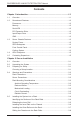
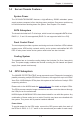
SUPERSERVER 2028GR-TR/TRT/TRH/TRHT User's Manual 1-2 Serverboard Features At the heart of the server is the X10DRG-H/HT, a dual processor serverboard based on the Intel PCH C612 chipset. Below are the main features. (See Figure 1-1 for a block diagram) Processors The X10DRG-H/HT supports two Intel E5-2600v3 series processors in LGA 2011 sockets (Socket R3). Refer to the serverboard description pages on our web site for a complete listing of supported processors (www.supermicro.com).
Chapter 1: Introduction 1-3 Server Chassis Features System Power The SC218GHTS-R2K03BP features a high-efficiency 2000W redundant power supply system composed of two hot-plug power modules. One power module may be removed without shutting down the system. See Chapter 6 for details. SATA Subsystem The chassis includes ten 2.5" drive bays, which house hot-swappable SATA drives. RAID 0, 1, 5 and 10 are supported (RAID 5 is not supported with Linux OS).
SUPERSERVER 2028GR-TR/TRT/TRH/TRHT User's Manual QPI P1 9.6G P1 QPI P0 9.6G Processor 2 DDR4 #1 #2 #3 DMI2 PVCCIO (1.05/0.95) from 3.3v PCI-E X16 G3 PCI-E X16 G3 (LAN REVERSE) PCI-EX16 G3 DMI2 4GB/s MAX:12.5W Sagevill: 9W STBY:2.5W RMII/NCSI P3V3_PCH P1V5_PCH 3.3v P1V05_PCH 5v P1V05_STBY 3.3v STBY 1.05 PCH 1.05 ASW 1.5 PCH PVCCIO 1.0/0.95 #6/7/8 #3 #9 #8 #7 #6 #5 #4 #3 #2 #1 #0 PCH 6.
Chapter 1: Introduction 1-5 Contacting Supermicro Headquarters Address: Super Micro Computer, Inc. 980 Rock Ave. San Jose, CA 95131 U.S.A. Tel: +1 (408) 503-8000 Fax: +1 (408) 503-8008 Email: marketing@supermicro.com (General Information) support@supermicro.com (Technical Support) Web Site: www.supermicro.com Europe Address: Super Micro Computer B.V. Het Sterrenbeeld 28, 5215 ML 's-Hertogenbosch, The Netherlands Tel: +31 (0) 73-6400390 Fax: +31 (0) 73-6416525 Email: sales@supermicro.
SUPERSERVER 2028GR-TR/TRT/TRH/TRHT User's Manual Notes 1-6
Chapter 2: Server Installation Chapter 2 Server Installation 2-1 Overview This chapter provides a quick setup checklist to get your system up and running. This quick setup assumes that your system has come to you with the processors and memory preinstalled. If your system is not already fully integrated with a serverboard, processors, system memory etc., please turn to the chapter or section noted in each step for details on installing specific components.
SUPERSERVER 2028GR-TR/TRT/TRH/TRHT User's Manual 2-4 • • • • Warnings and Precautions Rack Precautions Ensure that the leveling jacks on the bottom of the rack are fully extended to the floor with the full weight of the rack resting on them. In single rack installation, stabilizers should be attached to the rack. In multiple rack installations, the racks should be coupled together. Always make sure the rack is stable before extending a component from the rack.
Chapter 2: Server Installation • • • Use a regulating uninterruptible power supply (UPS) to protect the server from power surges, voltage spikes and to keep your system operating in case of a power failure. Allow the hot plug SATA drives and power supply modules to cool before touching them. Always keep the rack's front door and all panels and components on the servers closed when not servicing to maintain proper cooling.
SUPERSERVER 2028GR-TR/TRT/TRH/TRHT User's Manual 2-5 Installing the System into a Rack This section provides information on installing the chassis into a rack unit with the rails provided. There are a variety of rack units on the market, which may mean that the assembly procedure will differ slightly from the instructions provided. You should also refer to the installation instructions that came with the rack unit you are using. Note: This rail will fit a rack between 26.5" and 36.4" deep.
Chapter 2: Server Installation Releasing the Inner Rail Each inner rail has a locking latch. This latch prevents the server from coming completely out of the rack when when the chassis is pulled out for servicing. To mount the rail onto the chassis, first release the inner rail from the outer rails. Releasing Inner Rail from the Outer Rails 1. Pull the inner rail out of the outer rail until it is fully extended as illustrated below. 2. Press the locking tab down to release the inner rail. 3.
SUPERSERVER 2028GR-TR/TRT/TRH/TRHT User's Manual Installing the Inner Rails on the Chassis Installing the Inner Rails 1. Identify the left and right inner rails. They are labeled. 2. Place the inner rail firmly against the side of the chassis, aligning the hooks on the side of the chassis with the holes in the inner rail. 3. Slide the inner rail forward toward the front of the chassis until the quick release bracket snaps into place, securing the rail to the chassis. 4.
Chapter 2: Server Installation Installing the Outer Rails onto the Rack Installing the Outer Rails 1. Press upward on the locking tab at the rear end of the middle rail. 2. Push the middle rail back into the outer rail. 3. Hang the hooks on the front of the outer rail onto the square holes on the front of the rack. If desired, use screws to secure the outer rails to the rack. 4. Pull out the rear of the outer rail, adjusting the length until it just fits within the posts of the rack. 5.
SUPERSERVER 2028GR-TR/TRT/TRH/TRHT User's Manual Sliding the Chassis onto the Rack Rails Warning: Mounting the system into the rack requires at least two people to support the chassis during installation. Please follow safety recommendations printed on the rails. Installing the Chassis into a Rack 1. Extend the outer rails as illustrated above. 2. Align the inner rails of the chassis with the outer rails on the rack. 3. Slide the inner rails into the outer rails, keeping the pressure even on both sides.
Chapter 2: Server Installation 2-6 Checking the Serverboard Setup After you install the server in the rack, you should open the unit to make sure the serverboard is properly installed and all the connections have been made. Removing the Chassis Cover 1. Power down the system and disconnect the power cords from the rear of the power supplies. 2. Remove the screws securing the top cover to the chassis. 3. Slide the cover toward the rear of the chassis. 4. Lift the cover up and off the chassis.
SUPERSERVER 2028GR-TR/TRT/TRH/TRHT User's Manual 2-7 Checking the Chassis Setup Checking the Drives Next, you should check to make sure the hard drives have been properly installed and all connections have been made. You can add or remove hard drives from the drive carriers without having to remove the top chassis cover. Refer to Chapter 6. Checking the Airflow Airflow is provided by system fans.
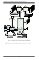
Chapter 3: System Interface Chapter 3 System Interface 3-1 Overview The chassis includes: • A control panel on the front that houses power buttons and status monitoring lights • Status lights on externally accessible hard drives • Status lights for the power supply visible from the back of the chassis These elements are described in this chapter with possible responses. Figure 3-1.
SUPERSERVER 2028GR-TR/TRT/TRH/TRHT User's Manual 3-2 Control Panel Buttons The control panel includes two push-buttons. Power: The main power switch is used to apply or remove power from the power supply to the server system. Turning off system power with this button removes the main power but keeps standby power supplied to the system. Therefore, you must unplug system before servicing. Reset: The reset button is used to reboot the system.
Chapter 3: System Interface 1 NIC1: Indicates network activity on GLAN1 or GLAN2 when flashing ! Power Fail: Indicates a power supply module has failed Information LED: Alerts operator of several states, as noted in the table below. Information LED Status Description Continuously on and red An overheat condition has occured. (This may be caused by cable congestion.) Blinking red (1Hz) Fan failure, check for an inoperative fan. Blinking red (0.
SUPERSERVER 2028GR-TR/TRT/TRH/TRHT User's Manual 3. Check the routing of the cables and make sure all fans are present and operating normally. 4. Verify that the heatsinks are installed properly. 3-4 Drive Carrier LEDs The chassis includes externally accessible SAS/SATA drives. Each drive carrier displays two status LEDs on the front of the carrier. • • 3-5 Green: When illuminated, this LED indicates drive activity.
Chapter 4: Warning Statements for AC Systems Chapter 4 Standardized Warning Statements for AC Systems About Standardized Warning Statements The following statements are industry standard warnings, provided to warn the user of situations which have the potential for bodily injury. Should you have questions or experience difficulty, contact Supermicro's Technical Support department for assistance. Only certified technicians should attempt to install or configure components.
SUPERSERVER 2028GR-TR/TRT/TRH/TRHT User's Manual Warnung WICHTIGE SICHERHEITSHINWEISE Dieses Warnsymbol bedeutet Gefahr. Sie befinden sich in einer Situation, die zu Verletzungen führen kann. Machen Sie sich vor der Arbeit mit Geräten mit den Gefahren elektrischer Schaltungen und den üblichen Verfahren zur Vorbeugung vor Unfällen vertraut.
Chapter 4: Warning Statements for AC Systems . تحذٌز!هذا الزهز ٌعًٌ خطز اًك فً حالة ٌوكي أى تتسبب فً اصابة جسذٌة كي على علن بالوخاطز الٌاجوة عي الذوائز،قبل أى تعول على أي هعذات الكهزبائٍة وكي على دراٌة بالووارسات الىقائٍة لوٌع وقىع أي حىادث استخذم رقن البٍاى الوٌصىص فً ًهاٌة كل تحذٌز للعثىر تزجوتها 안전을 위한 주의사항 경고! 이 경고 기호는 위험이 있음을 알려 줍니다. 작업자의 신체에 부상을 야기 할 수 있는 상태에 있게 됩니다. 모든 장비에 대한 작업을 수행하기 전에 전기회로와 관련된 위험요소들을 확인하시고 사전에 사고를 방지할 수 있도록 표준 작업절차를 준수해 주시기 바랍니다.
SUPERSERVER 2028GR-TR/TRT/TRH/TRHT User's Manual Installation Instructions Warning! Read the installation instructions before connecting the system to the power source. 設置手順書 システムを電源に接続する前に、設置手順書をお読み下さい。 警告 将此系统连接电源前,请先阅读安装说明。 警告 將系統與電源連接前,請先閱讀安裝說明。 Warnung Vor dem Anschließen des Systems an die Stromquelle die Installationsanweisungen lesen. ¡Advertencia! Lea las instrucciones de instalación antes de conectar el sistema a la red de alimentación.
Chapter 4: Warning Statements for AC Systems Circuit Breaker Warning! This product relies on the building's installation for short-circuit (overcurrent) protection. Ensure that the protective device is rated not greater than: 250 V, 20 A.
SUPERSERVER 2028GR-TR/TRT/TRH/TRHT User's Manual 경고! 이 제품은 전원의 단락(과전류)방지에 대해서 전적으로 건물의 관련 설비에 의존합니다. 보호장치의 정격이 반드시 250V(볼트), 20A(암페어)를 초과하지 않도록 해야 합니다. Waarschuwing Dit product is afhankelijk van de kortsluitbeveiliging (overspanning) van uw electrische installatie. Controleer of het beveiligde aparaat niet groter gedimensioneerd is dan 220V, 20A.
Chapter 4: Warning Statements for AC Systems ¡Advertencia! El sistema debe ser disconnected de todas las fuentes de energía y del cable eléctrico quitado de los módulos de fuente de alimentación antes de tener acceso el interior del chasis para instalar o para quitar componentes de sistema. Attention Le système doit être débranché de toutes les sources de puissance ainsi que de son cordon d'alimentation secteur avant d'accéder à l'intérieur du chassis pour installer ou enlever des composants de systéme.
SUPERSERVER 2028GR-TR/TRT/TRH/TRHT User's Manual Equipment Installation Warning! Only trained and qualified personnel should be allowed to install, replace, or service this equipment. 機器の設置 トレーニングを受け認定された人だけがこの装置の設置、交換、 またはサービスを許可 されています。 警告 只有经过培训且具有资格的人员才能进行此设备的安装、更换和维修。 警告 只有經過受訓且具資格人員才可安裝、更換與維修此設備。 Warnung Das Installieren, Ersetzen oder Bedienen dieser Ausrüstung sollte nur geschultem, qualifiziertem Personal gestattet werden.
Chapter 4: Warning Statements for AC Systems Waarschuwing Deze apparatuur mag alleen worden geïnstalleerd, vervangen of hersteld door geschoold en gekwalificeerd personeel. Restricted Area Warning! This unit is intended for installation in restricted access areas. A restricted access area can be accessed only through the use of a special tool, lock and key, or other means of security. (This warning does not apply to workstations).
SUPERSERVER 2028GR-TR/TRT/TRH/TRHT User's Manual אזור עם גישה מוגבלת !אזהרה הגישה ניתנת בעזרת.יש להתקין את היחידה באזורים שיש בהם הגבלת גישה .)' מנעול וכד,כלי אבטחה בלבד (מפתח . تم تخصيص هذه انىحذة نتركُبها فٍ مناطق محظورة ،َمكن انىصىل إنً منطقت محظورة فقط من خالل استخذاو أداة خاصت قفم ومفتاح أو أٌ وسُهت أخري نالمألما 경고! 이 장치는 접근이 제한된 구역에 설치하도록 되어있습니다. 특수도구, 잠금 장치 및 키, 또는 기타 보안 수단을 통해서만 접근 제한 구역에 들어갈 수 있습니다.
Chapter 4: Warning Statements for AC Systems Warnung Bei Einsetzen einer falschen Batterie besteht Explosionsgefahr. Ersetzen Sie die Batterie nur durch den gleichen oder vom Hersteller empfohlenen Batterietyp. Entsorgen Sie die benutzten Batterien nach den Anweisungen des Herstellers. Attention Danger d'explosion si la pile n'est pas remplacée correctement. Ne la remplacer que par une pile de type semblable ou équivalent, recommandée par le fabricant.
SUPERSERVER 2028GR-TR/TRT/TRH/TRHT User's Manual Redundant Power Supplies Warning! This unit might have more than one power supply connection. All connections must be removed to de-energize the unit. 冗長電源装置 このユニットは複数の電源装置が接続されている場合があります。 ユニットの電源を切るためには、すべての接続を取り外さなければなりません。 警告 此部件连接的电源可能不止一个,必须将所有电源断开才能停止给该部件供电。 警告 此裝置連接的電源可能不只一個,必須切斷所有電源才能停止對該裝置的供電。 Warnung Dieses Gerät kann mehr als eine Stromzufuhr haben.
Chapter 4: Warning Statements for AC Systems .قد يكون لهذا الجهاز عدة اتصاالت بوحدات امداد الطاقة يجب إزالة كافة االتصاالت لعسل الوحدة عن الكهرباء 경고! 이 장치에는 한 개 이상의 전원 공급 단자가 연결되어 있을 수 있습니다. 이 장치에 전원을 차단하기 위해서는 모든 연결 단자를 제거해야만 합니다. Waarschuwing Deze eenheid kan meer dan één stroomtoevoeraansluiting bevatten. Alle aansluitingen dienen verwijderd te worden om het apparaat stroomloos te maken.
SUPERSERVER 2028GR-TR/TRT/TRH/TRHT User's Manual מתח בפנל האחורי !אזהרה יש להיזהר במהלך.קיימת סכנת מתח בפנל האחורי בזמן תפעול המערכת .העבודה هناك خطز مه التيار الكهزبائي أوالطاقة المىجىدة على اللىحة عندما يكىن النظام يعمل كه حذرا عند خدمة هذا الجهاس 경고! 시스템이 동작 중일 때 후면판 (Backplane)에는 위험한 전압이나 에너지가 발생 합니다. 서비스 작업 시 주의하십시오. Waarschuwing Een gevaarlijke spanning of energie is aanwezig op de backplane wanneer het systeem in gebruik is. Voorzichtigheid is geboden tijdens het onderhoud.
Chapter 4: Warning Statements for AC Systems Attention L'équipement doit être installé conformément aux normes électriques nationales et locales. תיאום חוקי החשמל הארצי !אזהרה .התקנת הציוד חייבת להיות תואמת לחוקי החשמל המקומיים והארציים تركيب المعدات الكهربائية يجب أن يمتثل للقىاويه المحلية والىطىية المتعلقة بالكهرباء 경고! 현 지역 및 국가의 전기 규정에 따라 장비를 설치해야 합니다. Waarschuwing Bij installatie van de apparatuur moet worden voldaan aan de lokale en nationale elektriciteitsvoorschriften.
SUPERSERVER 2028GR-TR/TRT/TRH/TRHT User's Manual ¡Advertencia! Al deshacerse por completo de este producto debe seguir todas las leyes y reglamentos nacionales. Attention La mise au rebut ou le recyclage de ce produit sont généralement soumis à des lois et/ou directives de respect de l'environnement. Renseignez-vous auprès de l'organisme compétent. סילוק המוצר !אזהרה .
Chapter 4: Warning Statements for AC Systems 警告 當您從機架移除風扇裝置,風扇可能仍在轉動。小心不要將手指、螺絲起子和其他 物品太靠近風扇。 Warnung Die Lüfter drehen sich u. U. noch, wenn die Lüfterbaugruppe aus dem Chassis genommen wird. Halten Sie Finger, Schraubendreher und andere Gegenstände von den Öffnungen des Lüftergehäuses entfernt. ¡Advertencia! Los ventiladores podran dar vuelta cuando usted quite ell montaje del ventilador del chasis.
SUPERSERVER 2028GR-TR/TRT/TRH/TRHT User's Manual Power Cable and AC Adapter Warning! When installing the product, use the provided or designated connection cables, power cables and AC adaptors. Using any other cables and adaptors could cause a malfunction or a fire. Electrical Appliance and Material Safety Law prohibits the use of UL or CSA -certified cables (that have UL/CSA shown on the code) for any other electrical devices than products designated by Supermicro only.
Chapter 4: Warning Statements for AC Systems Attention Lors de l'installation du produit, utilisez les bables de connection fournis ou désigné. L'utilisation d'autres cables et adaptateurs peut provoquer un dysfonctionnement ou un incendie. Appareils électroménagers et de loi sur la sécurité Matériel interdit l'utilisation de UL ou CSA câbles certifiés qui ont UL ou CSA indiqué sur le code pour tous les autres appareils électriques que les produits désignés par Supermicro seulement.
SUPERSERVER 2028GR-TR/TRT/TRH/TRHT User's Manual Notes 4-20
Chapter 5: Advanced Serverboard Setup Chapter 5 Advanced Serverboard Setup This chapter covers the steps required to connect cables and describes all jumpers and connections. A layout and quick reference chart are included in this chapter for your reference. Always close the chassis when you have finished working on the system to maintain optimal cooling. The 2028GR-TR/TRH uses the X10DRG-H serverboard, and the 2028GR-TRT/ TRHT uses the X10DRG-HT serverboard.
SUPERSERVER 2028GR-TR/TRT/TRH/TRHT User's Manual 5-2 Connecting Cables Assuming the X10DRG-H/HT serverboard is installed, the next step is to connect the cables to the board. These include the data (ribbon) cables for the peripherals and control panel and the power cables. Connecting Data Cables The ribbon cables used to transfer data from the peripheral devices have been carefully routed to prevent them from blocking the flow of cooling air that moves through the system from front to back.
Chapter 5: Advanced Serverboard Setup 5-3 I/O Ports 13 2 14 15 16 17 1 Figure 5-1. I/O Ports IO Ports 1. USB Port 0 5. LAN Port 2 2. USB Port 1 6. VGA Port 3. IPMI Dedicated LAN 7. UID Switch 4. LAN Port 1 For X10DRG-H the LAN ports are 1Gb; for X10DRG-HT the LAN ports are 10Gb.
SUPERSERVER 2028GR-TR/TRT/TRH/TRHT User's Manual 5-4 Installing the Processor and Heatsink Notes: • • Always remove the power cord before adding, removing or changing a CPU. When receiving a serverboard without a processor pre-installed, make sure that the plastic CPU socket cap is in place and none of the socket pins are bent; otherwise, contact your retailer immediately. • If you buy a CPU separately, use only an Intel-certified, multi-directional heatsink.
Chapter 5: Advanced Serverboard Setup 3. W ith the sec ond lever f ully retracted, gently push down on the "Open 1st" lever to loosen the load plate. Lift the load plate with your fingers to open it completely. Open the load plate. 4. Pop the plastic c ap mar ked "Warning" out of the load plate. IMPORTANT! 5. Holding the CPU carefully above the socket, orient the CPU so that all keys and edges will fit the socket. OP EN 1st 6. Carefully lower the CPU straight down into the socket.
SUPERSERVER 2028GR-TR/TRT/TRH/TRHT User's Manual Gently close the load plate. 7. With the "Close 1st" lever fully retracted, gently close the load plate. 8. Make sure the locking mechanism on the "Close 1st" lever catches the lip of the load plate. Close and lock the "Close 1st" lever. Push down and lock the lever labeled "Close 1st". OP EN 1st Engage the lip of the load plate and locking portion of the lever." 9. Close and lock the "Open 1st" lever.
Chapter 5: Advanced Serverboard Setup Installing a CPU Heatsink 1. Remove power from the system 2 and unplug the AC power cord from the power supply. 4 2. Do not apply any thermal grease to the heatsink or the CPU die; the required amount has already been applied. 3 3. Place the heatsink on top of the CPU so that the four mounting holes are aligned with those on the (preinstalled) heatsink retention mechanism. 4. Screw in two diagonal screws until just snug.
SUPERSERVER 2028GR-TR/TRT/TRH/TRHT User's Manual 5-5 Installing Memory Caution: Exercise care installing or removing DIMM modules to avoid damage. Installing Memory Modules Insert the desired number of DIMMs into the memory slots, starting with P1-DIMM 1A 1. Push the release tabs outwards on both ends of the DIMM slot to unlock it. 2. Align the key on the DIMM module with the receptive point on the slot. 3.
Chapter 5: Advanced Serverboard Setup Processors and their Corresponding Memory Modules CPU# Corresponding DIMM Modules CPU 1 P1DIMMA1 P1DIMMB1 P1DIMMC1 P1DIMMD1 P1DIMMA2 P1DIMMB2 P1DIMMC2 P1DIMMD2 CPU2 P2DIMME1 P2DIMMF1 P2DIMMG1 P2DIMMH1 P2DIMME2 P2DIMM F2 P2DIMMG2 P2DIMMH2 Processor and Memory Module Population for Optimal Performance Number of CPUs+DIMMs CPU and Memory Population Configuration Table 1 CPU & 2 DIMMs CPU1 P1-DIMMA1/P1-DIMMB1 1 CPU & 4 DIMMs CPU1 P1-DIMMA1/P1-DIMMB
SUPERSERVER 2028GR-TR/TRT/TRH/TRHT User's Manual Serverboard Details 5-6 USB2/3(3.0) USB0/1 JPL1 JVRM1 JVRM2 J23 P1 DIMMC1 P1 DIMMC2 P1 DIMMD1 P1 DIMMD2 JPF1 JPF2 JSPK1 JBR1 JPME2 JSTBY1 CLOSE 1st S-SATA0 S-SATA1 S-SATA2 S-SATA3 P1 DIMME1 P1 DIMME2 P1 DIMMF1 P1 DIMMF2 JPW2 FANH FANG JPW7 FANE FAN1 P1 DIMMH2 P1 DIMMH1 P1 DIMMG2 P1 DIMMG1 FAN2 CPU2 SLOT4 PCI-E 3.
Chapter 5: Advanced Serverboard Setup X10DRG-H(T) Jumpers Jumper Description Default Setting JBT1 Clear CMOS See section 5-8 JPB1 BMC Enable Pins 1-2 (Enabled) JPG1 VGA Enable Pins 1-2 (Enabled) JPL1 GLAN1/GLAN2 Enable (X10DRG-H) 10_GLAN1/10G_LAN2 Enable (X10DRG-HT) Pins 1-2 (Enabled) JPME2 Manufacture (ME) Mode Select Pins 1-2 (Normal) JWD1 Watch-Dog Timer Enable Pins 1-2 (Reset) X10DRG-H(T) Connectors Connectors Description Battery (BT1) Onboard CMOS Battery (See Chpt.
SUPERSERVER 2028GR-TR/TRT/TRH/TRHT User's Manual SW1 UID Switch (BP) USB 4/5 (3.0) Backpanel USB 3.0 Port 4/Port 5 (FP) 2/3 (3.0) Front Accessible USB 3.0 headers 0/1, 2/3 (FP) USB 0/1 (2.0) Front-Accessible USB 2.
Chapter 5: Advanced Serverboard Setup 5-7 Connector Definitions Power Connectors The X10DRG-H/HT serverboard has one proprietary main power (JPW1) and six 8-pin 12V power connectors (JPW2, JPW3/JPW4/JPW5/JPW6/JPW7). The 8-pin power connector located at JPW2 is used to supply power to the serverboard, and the other five 8-pin power connectors located at JPW3-JPW7 are used for HDD backplane and GPU add-on cards.
SUPERSERVER 2028GR-TR/TRT/TRH/TRHT User's Manual 20 19 Ground NMI x (Key) x (Key) Power On LED 3.3V HDD LED FP UID/3.3V Stby NIC1 LED (Link) NIC1 LED (Activity) NIC2 LED (Link) NIC2 LED (Activity) OH/Fan Fail/PWR Fail/UID LED Blue LED (UID Cathode) PWR Fail LED 3.3V Ground Reset (Button) Ground Power (Button) 2 1 Figure 5-4.
Chapter 5: Advanced Serverboard Setup NIC2 (LAN2) LED The LED connections for LAN2 are on pins 9 and 10 of JF1. Attach an LED cable to display network activity. See the table on the right for pin definitions. NIC1 (LAN1) LED The LED connections for LAN1 are on pins 11 and 12 of JF1. Attach an LED cable to display network activity. See the table on the right for pin definitions.
SUPERSERVER 2028GR-TR/TRT/TRH/TRHT User's Manual Fan Headers The serverboard has twelve fan headers. Fans 1~4 are for CPU/system use and Fans A~H for GPU use.. All are 4-pin fan headers, which are backward compatible with traditional 3-pin fans. However, fan speed control is available for 4-pin fans only. The fan speeds are controlled by Thermal Management via IPMI 2.0 interface. See the table on the right for pin definitions.
Chapter 5: Advanced Serverboard Setup Standby Power Header Standby PWR Pin Definitions The +5V Standby Power header is located at JSTBY1 on the motherboard. See the table on the right for pin definitions. (You must also have a card with a Standby Power connector and a cable to use this feature.
SUPERSERVER 2028GR-TR/TRT/TRH/TRHT User's Manual Universal Serial Bus (USB) Two USB 3.0 ports (USB 4/5) are located on the I/O rear I/O shield. In addition, two internal USB headers, provide four USB 3.0 connections (USB 0/1, USB 2/3) for front panel support. (Cables are not included). See the tables on the right for pin definitions.
Chapter 5: Advanced Serverboard Setup Unit Identifier Switch A Unit Identifier (UID) switch and two LED indicators are provided on the serverboard. The rear UID LED (LE4) is located next to the rear UID switch. The front panel UID switch and LED are described with JF1 connectors. Pressing a UID switch will turn on both the rear and front UID LEDs. Pressing a UID switch again will turn off both LEDs. These UIDs provide easy identification of a system unit that may be in need of service.
SUPERSERVER 2028GR-TR/TRT/TRH/TRHT User's Manual 5-8 Jumper Settings Explanation of Jumpers To modify the operation of the serverboard, jumpers can be used to choose between optional settings. Jumpers create shorts between two pins to change the function of the connector. Pin 1 is identified with a square solder pad on the printed circuit board. See the serverboard layout pages for jumper locations.
Chapter 5: Advanced Serverboard Setup VGA Enable/Disable JPG1 allows you to enable or disable the VGA port. The default position is on pins 1 and 2 to enable VGA. See the table on the right for jumper settings. VGA Enable/Disable Jumper Settings Jumper Setting Definition Pins 1-2 Enabled Pins 2-3 Disabled Watch Dog Enable/Disable JWD1 controls the Watch Dog function. Watch Dog is a system monitor that can reboot the system when a software application hangs.
SUPERSERVER 2028GR-TR/TRT/TRH/TRHT User's Manual 5-9 Onboard Indicators LAN 1/2 Activity LED Link LED LAN1/2 Port LEDs The Ethernet ports have two LEDs. On each port, one LED indicates activity and teh other indicates the speed of the connection. It may be green, amber or off to. See the table on the right for the functions associated with the connection speed LED.
Chapter 5: Advanced Serverboard Setup 5-10 SATA Ports SATA Port Pin Definitions SATA Ports There are ten SATA 3.0 (I-SATA 0-5 & S-SATA0-3) on the motherboard. I-SATA ports are supported by the Intel PCH C612, and S-SATA ports are supported by the Intel SCU chip. See the table on the right for pin definitions.
SUPERSERVER 2028GR-TR/TRT/TRH/TRHT User's Manual 5-11 Installing Software The Supermicro ftp site contains drivers and utilities for your system at ftp://ftp. supermicro.com. Some of these must be installed, such as the chipset driver. After accessing the ftp site, go into the CDR_Images directory and locate the ISO file for your serverboard. Download this file to create a CD/DVD of the drivers and utilities it contains. (You may also use a utility to extract the ISO file if preferred.
Chapter 5: Advanced Serverboard Setup SuperDoctor® 5 The Supermicro SuperDoctor 5 is a program that functions in a command-line or web-based interface in Windows and Linux operating systems. The program monitors system health information such as CPU temperature, system voltages, system power consumption, fan speed, and provides alerts via email or Simple Network Management Protocol (SNMP).
SUPERSERVER 2028GR-TR/TRT/TRH/TRHT User's Manual 5-12 Onboard Battery Care must be taken to assure that the chassis cover is in place when the system is operating to ensure proper cooling. Out of warranty damage to the system can occur if this practice is not strictly followed. OR Figure 5-8. Installing the Onboard Battery Please handle used batteries carefully. Do not damage the battery in any way; a damaged battery may release hazardous materials into the environment.
Chapter 6: Advanced Chassis Setup Chapter 6 Advanced Chassis Setup This chapter covers the steps required to install components and perform maintenance on the SC218GHTS-R2K03BP chassis. The only tool required is a Phillips screwdriver. Your system may require the installation of processors, memory, drives or expansion cards. Other procedures presented in this chapter are for maintenance or replacement. Hot-Swap Drive Bays (10) Control Panel PCI Slots Power Supplies Rear I/O Ports Figure 6-1.
SUPERSERVER 2028GR-TR/TRT/TRH/TRHT Series User's Manual 6-1 Static-Sensitive Devices Electrostatic Discharge (ESD) can damage electronic components. To prevent damage to any printed circuit boards (PCBs), it is important to handle them very carefully. The following measures are generally sufficient to protect your equipment from ESD damage. Precautions • • • • • • 6-2 Use a grounded wrist strap designed to prevent static discharge.
Chapter 6: Advanced Chassis Setup 6-3 Installing Drives Drive bays are accessible from the front of the chassis without removing the chassis cover or powering down the system. The hard disk drives are mounted in drive carriers to simplify their installation and removal from the chassis. These carriers also help promote proper airflow for the drive bays. For this reason, even carriers without drives installed must remain in the chassis during system operation.
SUPERSERVER 2028GR-TR/TRT/TRH/TRHT Series User's Manual Dummy Drive Hard Drive Carrier Figure 6-3. Removing a Dummy Drive from the Drive Carrier Installing a Hard Drive into a Drive Carrier 1. Remove the four screws securing the dummy drive to the hard drive carrier. 2. Insert a hard drive into the carrier with the PCB side facing down and the connector end toward the rear of the carrier.
Chapter 6: Advanced Chassis Setup Note: The hard drives are designated with numbers 0 through 9 from left to right. When setting up RAID, one RAID level may be applied to drives 0-3, 8 and 9 (the I-SATA drives) and one RAID level may be applied to drives 4-7 (the S-SATA drives). You may not apply a single RAID level across all eight drives. Caution: Except for short periods of time (swapping hard drives), do not operate the server with the hard drive carriers removed.
SUPERSERVER 2028GR-TR/TRT/TRH/TRHT Series User's Manual 6-4 Installing Graphics (GPU) Cards The chassis supports up to six GPU cards, which are mounted in brackets to fit into the PCI-Express slots at the front of the chassis. NVIDIA Kepler K10/K20/K40 GPUs are supported. The GPU cards may be preinstalled, the procedure below is provided if a GPU card must be replaced. See the NVIDIA web site for more details on the GPU specifications. Installing Graphics Cards 1.
Chapter 6: Advanced Chassis Setup Airflow Side Screws Left Side GPU Bracket and Cards Side Screws Right Side GPU Bracket and Cards Figure 6-6. Installing the Left and Right GPU Brackets into the Chassis Important Note for Kepler GPUs: Note the airflow arrows on top of the GPU card.
SUPERSERVER 2028GR-TR/TRT/TRH/TRHT Series User's Manual 6-5 Expansion Card Setup The system supports the following PCI-Express expansion cards and an expansion card bracket: Cards up to 10.5" in length are supported. • • Four PCIe 3.0 x16 (2028GR-TR/TRT), or six PCIe 3.0 x16 (2028GR-TRH/ TRHT) One PCIe 3.0 x8 (in x16) low-profile slot Low-Profile PCIe Slots Standard Size PCIe Slots Figure 6-8. Rear Expansion Card Slots Installing a Full-Height Expansion Card 1.
Chapter 6: Advanced Chassis Setup Figure 6-9. Installing Expansion Cards into the Expansion Card Bracket Figure 6-10.
SUPERSERVER 2028GR-TR/TRT/TRH/TRHT Series User's Manual Figure 6-11. Installing a Low-Profile Expansion Card Installing a Low-Profile Expansion Card 1. Disconnect the chassis from any power source. 2. Remove the screws securing the PCI slot cover and slide the cover sideways to remove it. 3. Insert the expansion card into the riser card. 4. Simultaneously slide the expansion card PCI slot bracket into the PCI slot and insert the riser card into the serverboard. 5.
Chapter 6: Advanced Chassis Setup 6-6 System Cooling Five 8-cm fans provide the cooling for the system. It is very important that the chassis top cover is properly installed and making a good seal in order for the cooling air to circulate properly through the chassis and cool the components. System Fan Failure Fan speed is controlled by system temperature by means of an IPMI setting. If a fan fails, the remaining fans will ramp up to full speed. The system can continue to run with a failed fan.
SUPERSERVER 2028GR-TR/TRT/TRH/TRHT Series User's Manual Replacing a System Fan 1. Remove the chassis cover. If necessary to determine which fan has failed, keep the power on. Then power-down the system and disconnect the chassis power cord. 2. Remove the screws securing the fan housing to the floor of the chassis. See the illustrations below to determine the location of the screws for the fan that is being removed. Set these screws aside for later use.
Chapter 6: Advanced Chassis Setup 3. Lift the fan housing up and out of the chassis. 4. Disconnect the fan cable. 5. Examine the drawings below, then disassemble the fan housing by removing the front and rear fan guards (A). 6. Reassemble the fan housing around the replacement fan as follows: Front and GPU Fans: Clip the front and rear fan guards (A) into the left and right side clips (B) 1A 1B 1A 1B Figure 6-13.
SUPERSERVER 2028GR-TR/TRT/TRH/TRHT Series User's Manual Installing the Air Shroud Air shrouds concentrate airflow to maximize fan efficiency. The serverboard air shroud does not require screws for installation. Each GPU card has its own air shroud. Installing the Serverboard Air Shroud 1. Lay the chassis on a flat, stable surface and remove the chassis cover. 2. Ensure that the motherboard, CPU, heatsink and memory are all properly installed. 3.
Chapter 6: Advanced Chassis Setup 6-7 Power Supply The system includes a dual hot-plug 2000Watt power modules. They automatically sense the input voltage between 100v to 240v, and operate at that voltage. Note that different input voltages will result in different maximum power output levels. In the event of a power supply failure, the remaining power supply will automatically take over. The failed power module can be replaced without powering-down the system. Replace with the same model.
SUPERSERVER 2028GR-TR/TRT/TRH/TRHT Series User's Manual Notes 6-16
Chapter 7: AMI BIOS Chapter 7 BIOS 7-1 Introduction This chapter describes the AMI BIOS setup utility for the X10DRG-H/HT. The ROM BIOS is stored in a Flash EEPROM and can be easily updated. This chapter describes the basic navigation of the AMI BIOS setup utility screens. Note: For AMI BIOS recovery, please refer to the UEFI BIOS Recovery Instructions in Appendix C. Starting BIOS Setup Utility To enter the AMI BIOS setup utility screens, press the key while the system is booting up.
SuperServer 2028GR-TR/TRT/TRH/TRHT User’s Manual How to Start the Setup Utility Normally, the only visible Power-On Self-Test (POST) routine is the memory test. As the memory is being tested, press the key to enter the main menu of the AMI BIOS setup utility. From the main menu, you can access the other setup screens. An AMI BIOS identification string is displayed at the left bottom corner of the screen, below the copyright message.
Chapter 7: AMI BIOS The following Main menu items will be displayed: System Date/System Time Use this option to change the system date and time. Highlight System Date or System Time using the arrow keys. Enter new values using the keyboard. Press the key or the arrow keys to move between fields. The date must be entered in Day MM/DD/YYYY format. The time is entered in HH:MM:SS format. Note: The time is in the 24-hour format. For example, 5:30 P.M. appears as 17:30:00.
SuperServer 2028GR-TR/TRT/TRH/TRHT User’s Manual 7-3 Advanced Setup Configurations Use the arrow keys to select Advanced setup and press to access the submenu items: Caution: Take Caution when changing the Advanced settings. An incorrect value, a very high DRAM frequency or an incorrect BIOS timing setting may cause the system to malfunction. When this occurs, restore the setting to the manufacture default setting.
Chapter 7: AMI BIOS Wait For 'F1' If Error Select Enabled to force the system to wait until the 'F1' key is pressed if an error occurs. The options are Disabled and Enabled. INT19 (Interrupt 19) Trap Response Interrupt 19 is the software interrupt that handles the boot disk function. When this item is set to Immediate, the ROM BIOS of the host adaptors will "capture" Interrupt 19 at bootup immediately and allow the drives that are attached to these host adaptors to function as bootable disks.
SuperServer 2028GR-TR/TRT/TRH/TRHT User’s Manual CPU Configuration This submenu displays the following CPU information as detected by the BIOS. It also allows the user to configure CPU settings.
Chapter 7: AMI BIOS codes to overwhelm the processor to damage the system during an attack. This feature is used in conjunction with the items: "Clear MCA," "VMX," "Enable SMX," and "Lock Chipset" for Virtualization media support. The options are Enable and Disable. (Refer to Intel and Microsoft websites for more information.) PPIN Control Select Unlock/Enable to use the Protected-Processor Inventory Number (PPIN) in the system. The options are Unlock/Enable and Unlock/Disable.
SuperServer 2028GR-TR/TRT/TRH/TRHT User’s Manual AES-NI Select Enable to use the Intel Advanced Encryption Standard (AES) New Instructions (NI) to ensure data security. The options are Enable and Disable. Intel Virtualization Technology Select Enable to use Intel Virtualization Technology support for Direct I/O VT-d support by reporting the I/O device assignments to the VMM (Virtual Machine Monitor) through the DMAR ACPI tables.
Chapter 7: AMI BIOS No PCIe Port Active ECO This item provides a workaround solution when there is no PCIe port active. The options are Reset the SQ FLOP by CSR Option and PCU Squelch Exit Ignore Option. Socket 0 PCIED00F0 Port 0/DMI This submenu allows the user to configure the settings for the following PCI-E prots: 0, 1A, 1B, 2A, 2B, 2C, 2D, 3A, 3B, 3C, and 3D. Link Speed Use this item to configure the link speed of a PCI-E device installed on the PCI-E slot specified by the user.
SuperServer 2028GR-TR/TRT/TRH/TRHT User’s Manual Corr Err Over (Correctable Error Overwrite) This item configures the option to overwrite correctable errors for ECC memory. The options are Disable and Enable. L0s Support This item configures the option to enable support for the L0s PCI-E link state (non supported in this motherboard). The only available option is Disable.
Chapter 7: AMI BIOS QPI (Quick Path Interconnect) Configuration QPI General Configuration QPI Status The following information will display: • Number of CPU • Number of IIO • Current QPI Link Speed • Current QPI Link Frequency • QPI Global MMIO Low Base/Limit • QPI Global MMIO High Base/Limit • QPI PCIe Configuration Base/Size Link Frequency Select Use this item to select the desired frequency for QPI Link connections. The options are 6.4GB/s, 8.0GB/s, 9.6GB/s, Auto, and Auto Limited.
SuperServer 2028GR-TR/TRT/TRH/TRHT User’s Manual Memory Configuration Enforce POR Select Enable to enforce POR restrictions on memory frequency and voltage programming. The options are Enabled and Disabled. Memory Frequency Use this feature to set the maximum memory frequency for onboard memory modules. The options are Auto, 1333, 1400, 1600, 1800, 1867, 2000, 2133, 2200, 2400, 2600, 2667, 2800, 2993, 3000, 3200 and Reserved (Do not select Reserved).
Chapter 7: AMI BIOS RAS Mode When Disable is selected, RAS is not supported. When Mirror is selected, the motherboard maintains two identical copies of all data in memory for data backup. When Lockstep is selected, the motherboard uses two areas of memory to run the same set of operations in parallel to boost performance. The options are Disable, Mirror, and Lockstep Mode. Memory Rank Sparing Select Enable to enable memory-sparing support for memory ranks to improve memory performance.
SuperServer 2028GR-TR/TRT/TRH/TRHT User’s Manual Legacy USB Support Select Enabled to support onboard legacy USB devices. Select Auto to disable legacy support if there are no legacy USB devices present. Select Disable to have all USB devices available for EFI applications only. The options are Enabled, Disabled, and Auto. XHCI (Extensible Host Controller Interface) Hand-Off This is a work-around solution for operating systems that do not support XHCI (Extensible Host Controller Interface) hand-off.
Chapter 7: AMI BIOS SATA Configuration When this submenu is selected, AMI BIOS automatically detects the presence of the SATA devices that are supported by the Intel PCH chip and displays the following items: SATA Controller This item enables or disables the onboard SATA controller supported by the Intel PCH chip. The options are Enabled and Disabled. Configure SATA as Select IDE to configure a SATA drive specified by the user as an IDE drive.
SuperServer 2028GR-TR/TRT/TRH/TRHT User’s Manual *If the item above "Configure SATA as" is set to IDE, the following items will display: Serial ATA Port 0 ~ Port 5 This item indicates that a SATA port specified by the user is installed (present) or not. Port 0 ~ Port 5 SATA Device Type (Available when a SATA port is detected) Use this item to specify if the SATA port specified by the user should be connected to a Solid State drive or a Hard Disk Drive. The options are Hard Disk Drive and Solid State Drive.
Chapter 7: AMI BIOS Port 0 ~ Port 5 Spin Up Device On an edge detect from 0 to 1, set this item to allow the PCH to start a COMRESET initialization to the device. The options are Enabled and Disabled. Port 0 ~ Port 5 SATA Device Type Use this item to specify if the SATA port specified by the user should be connected to a Solid State drive or a Hard Disk Drive. The options are Hard Disk Drive and Solid State Drive.
SuperServer 2028GR-TR/TRT/TRH/TRHT User’s Manual sSATA Port 0 ~ Port 3 Spin Up Device On an edge detect from 0 to 1, set this item to allow the PCH to start a COMRESET initialization to the device. The options are Enabled and Disabled. Port 0 ~ Port 3 sSATA Device Type Use this item to specify if the sSATA port specified by the user should be connected to a Solid State drive or a Hard Disk Drive. The options are Hard Disk Drive and Solid State Drive.
Chapter 7: AMI BIOS • Model number of drive and capacity • Software Preserve Support sSATA Port 0 ~ Port 3 Select Enabled to enable an sSATA port specified by the user. The options are Disabled and Enabled. sSATA Port 0 ~ Port 3 Spin Up Device On an edge detect from 0 to 1, set this item to allow the PCH to start a COMRESET initialization to the device. The options are Enabled and Disabled.
SuperServer 2028GR-TR/TRT/TRH/TRHT User’s Manual PCIe/PCI/PnP Configuration PCI Devices Common Settings PCI Latency Timer Select Enabled to set the latency timer for PCI. The options are 32 PCI Bus Clocks, 64 PCI Bus Clocks, 96 PCI Bus Clocks, 128 PCI Bus Clocks, 160 PCI Bus Clocks, 192 PCI Bus Clocks, 224 PCI Bus Clocks, and 248 PCI Bus Clocks. PERR# Generation Select Enabled to support PERR (PCI/PCI-E Parity Error)/SERR (System Error) runtime error reporting for a PCI/PCI-E slot.
Chapter 7: AMI BIOS ASPM Support Use this item to set the Active State Power Management (ASPM) level for a PCI-E device. Select Auto for the system BIOS to automatically set the ASPM level based on the system configuration. Select Disabled to disable ASPM support. The options are Disabled and Auto. Warning: Enabling ASPM support may cause some PCI-E devices to fail! MMIOHBase Use this item to select the base memory size according to memory-address mapping for the PCH.
SuperServer 2028GR-TR/TRT/TRH/TRHT User’s Manual VGA Priority Use this item to select the graphics device to be used as the primary video display for system boot. The options are Onboard and Offboard. Onboard LAN Option ROM Type Select Legacy to boot the computer using a Legacy device installed on the motherboard. The options are Legacy and EFI.
Chapter 7: AMI BIOS Serial Port 2 Attribute Select SOL to use COM Port 2 as a Serial_Over_LAN (SOL) port for console redirection. The options are COM and SOL. Serial Port Console Redirection COM 1 COM 1 Console Redirection Select Enabled to enable COM Port 1 Console Redirection, which will allow a client machine to be connected to a host machine at a remote site for networking. The options are Disabled and Enabled.
SuperServer 2028GR-TR/TRT/TRH/TRHT User’s Manual the data bits. Select Space to add a Space as a parity bit to be sent with your data bits. The options are None, Even, Odd, Mark, and Space. Stop Bits A stop bit indicates the end of a serial data packet. Select 1 Stop Bit for standard serial data communication. Select 2 Stop Bits if slower devices are used. The options are 1 and 2. Flow Control Use this item to set the flow control for Console Redirection to prevent data loss caused by buffer overflow.
Chapter 7: AMI BIOS SOL/COM2 Console Redirection SOL/COM2 Console Redirection Select Enabled to use the SOL/COM2 port for Console Redirection. The options are Enabled and Disabled. *If the item above set to Enabled, the following items will become available for user's configuration: SOL/COM2 Console Redirection Settings Use this feature to specify how the host computer will exchange data with the client computer, which is the remote computer used by the user.
SuperServer 2028GR-TR/TRT/TRH/TRHT User’s Manual Flow Control Use this feature to set the flow control for Console Redirection to prevent data loss caused by buffer overflow. Send a "Stop" signal to stop sending data when the receiving buffer is full. Send a "Start" signal to start data-sending when the receiving buffer is empty. The options are None and Hardware RTS/CTS. VT-UTF8 Combo Key Support Select Enabled to enable VT-UTF8 Combination Key support for ANSI/VT100 terminals.
Chapter 7: AMI BIOS Serial Port for Out-of-Band Management / Windows Emergency Management Services (EMS) The submenu allows the user to configure Console Redirection settings to support Out-of-Band Serial Port management. Console Redirection Select Enabled to use a COM port selected by the user for EMS Console Redirection. The options are Enabled and Disabled.
SuperServer 2028GR-TR/TRT/TRH/TRHT User’s Manual The setting for each of the following features is displayed: Data Bits, Parity, Stop Bits Trusted Computing (Available when a TPM device is installed and detected by the BIOS) Configuration Security Device Support If this feature and the TPM jumper on the motherboard are both set to Enabled, onboard security devices will be enabled for TPM (Trusted Platform Module) support to enhance data integrity and network security.
Chapter 7: AMI BIOS pendency on other timestamp calculation devices, such as an x86 RDTSC Instruction embedded in the CPU. The High Performance Event Timer is used to replace the 8254 Programmable Interval Timer. The options are Enabled and Disabled. NUMA (Available when the OS supports this feature) Select Enabled to enable Non-Uniform Memory Access support to enhance system performance. The options are Enabled and Disabled.
SuperServer 2028GR-TR/TRT/TRH/TRHT User’s Manual 7-4 Event Logs Use this feature to configure Event Log settings. Change SMBIOS Event Log Settings This feature allows the user to configure SMBIOS Event settings. Enabling/Disabling Options SMBIOS Event Log Select Enabled to enable SMBIOS (System Management BIOS) Event Logging during system boot. The options are Enabled and Disabled. Runtime Error Logging Support Select Enable to support Runtime Error Logging. The options are Enable and Disable.
Chapter 7: AMI BIOS Memory Correctable Error Threshold Use this item to enter the threshold value for correctable memory errors. The default setting is 10. Erasing Settings Erase Event Log Select Enabled to erase all error events in the SMBIOS (System Management BIOS) log before an event logging is initialized at bootup. The options are No and Yes. When Log is Full Select Erase Immediately to immediately erase all errors in the SMBIOS event log when the event log is full.
SuperServer 2028GR-TR/TRT/TRH/TRHT User’s Manual 7-5 IPMI Use this feature to configure Intelligent Platform Management Interface (IPMI) settings. IPMI Firmware Revision This item indicates the IPMI firmware revision used in your system. Status of BMC This item indicates the status of the onboard BMC (Baseboard Management Controller). System Event Log Enabling/Disabling Options SEL Components Select Enabled to enable all system event logging support at bootup. The options are Enabled and Disabled.
Chapter 7: AMI BIOS When SEL is Full This feature allows the user to determine what the AMI BIOS should do when the system event log is full. Select Erase Immediately to erase all events in the log when the system event log is full. The options are Do Nothing and Erase Immediately. Note: After making changes on a setting, be sure to reboot the system for the changes to take effect.
SuperServer 2028GR-TR/TRT/TRH/TRHT User’s Manual 7-6 Security Settings This menu allows the user to configure the following security settings for the system. Administrator Password Use this feature to set the administrator password which is required before the user entering the BIOS setup utility. The length of the password should be from 3 characters to 20 characters long. User Password Use this feature to set the user password which is required to enter the BIOS setup utility.
Chapter 7: AMI BIOS 7-7 Boot Settings Use this feature to configure Boot Settings: Boot Configuration Boot Mode Select Use this item to select the type of device to be used for system boot. The options are Legacy, UEFI, and Dual. Fixed Boot Order Priorities This option prioritizes the order of bootable devices from which the system will boot. Press on each entry from top to bottom to select devices.
SuperServer 2028GR-TR/TRT/TRH/TRHT User’s Manual • Dual Boot Order #9 • Dual Boot Order #10 • Dual Boot Order #11 • Dual Boot Order #12 • Dual Boot Order #13 • Dual Boot Order #14 • Dual Boot Order #15 Add New Boot Option Use this item to select a new boot device to add to the boot priority list. Add Boot Option Select the target boot device to add to the boot priority list. Path for Boot Option Select the device path (-the file system) for the new boot device to use.
Chapter 7: AMI BIOS • Boot Order #2 Network Drive BBS Priorities • Boot Order #1 UEFI Application Boot Priorities • UEFI Boot Order #1 7-37
SuperServer 2028GR-TR/TRT/TRH/TRHT User’s Manual 7-8 Save & Exit Select the Save & Exit tab from the BIOS setup screen to configure the settings below. Discard Changes and Exit Select this option to quit the BIOS setup without making any permanent changes to the system configuration, and reboot the computer. Select Discard Changes and Exit from the Exit menu and press .
Chapter 7: AMI BIOS Restore Optimized Defaults To set this feature, select Restore Optimized Defaults from the Exit menu and press . These are manufacture default settings designed for maximum system performance but not for maximum stability. Save as User Defaults To set this feature, select Save as User Defaults from the Exit menu and press . This enables the user to save any changes to the BIOS setup for future use.
SuperServer 2028GR-TR/TRT/TRH/TRHT User’s Manual Notes 7-40
Appendix A: BIOS Error Beep Codes Appendix A BIOS Error Beep Codes During the POST (Power-On Self-Test) routines, which are performed at each system boot, errors may occur. Non-fatal errors are those which, in most cases, allow the system to continue to boot. The error messages normally appear on the screen. Fatal errors will not allow the system to continue with bootup procedure. If a fatal error occurs, you should consult with your system manufacturer for possible repairs.
SUPERSERVER 2028GR-TR/TRT/TRH/TRHT User's Manual Notes A-2
Appendix B: System Specifications Appendix B System Specifications Processors Two Intel E5-2600v3 series processors in LGA 2011 sockets Note: Please refer to our web site for a complete listing of supported processors. Chipset Intel PCH C612 BIOS 128Mb SPI Flash EEPROM with AMI® BIOS Memory Capacity Sixteen DIMM sockets supporting up to 1TB of 288-pin Registered (RDIMM)/ Load Reduced (LRDIMM) DDR4 ECC 2133/1866/1600 MHz Drive Bays Ten 2.
SUPERSERVER 2028GR-TR/TRT/TRH/TRHT User's Manual Serverboard X10DRG-H/HT (proprietary ATX form factor) Dimensions: 19.8" (L) x 9.2" (W) (503 mm x 234 mm) Chassis SC218GHTS-R2K03BP (2U rackmount) Dimensions: (WxHxD) 17.2 x 3.5 x 30.5 in. (437 x 89 x 775 mm) System Cooling Five sets of 8-cm fans (fan speed controlled by IPMI) System Input Requirements AC Input Voltage: 100-240 VAC Rated Input Current: 1000W: 100-120V/12.5A max., 2000W: 230-240V/10A max.
Appendix B: System Specifications Dioxide) Lithium coin cells. “Perchlorate Material-special handling may apply. See www.dtsc.ca.
SUPERSERVER 2028GR-TR/TRT/TRH/TRHT User's Manual Notes B-4