
Computer Hardware User Manual

2-6
SUPER PIIIDM6/PIIIDM4/PIIIDM3/PIIIDME User's Manual
Installation
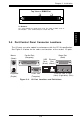
Front Control Panel
PWR_LED
Speaker
I2C
NIC
JF1
Keyboard
Lock
IDE LED
1
34
USB0
PWR_ON
Reset
Unused
Overheat
LED
Chassis
Intrusion
Unused
2
33
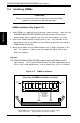
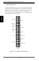
JF1 contains header pins for various front control panel connectors.
See Figure 2-4 for the pin definitions of the speaker, overheat LED,
keyboard lock, chassis intrusion, I2C, USB0, reset, power on, hard
drive LED and power LED headers, which are all located on JF1.
Please note that even and odd numbered pins are on opposite sides.
Refer to pages 2-7 to 2-8 for details.
Figure 2-4. Front Control Panel Connectors