
Computer Hardware User Manual

2-12
SUPER PIIIDM6/PIIIDM4/PIIIDM3/PIIIDME User's Manual
Installation
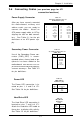
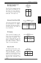
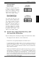
Wake-On-Ring
The Wake-On-Ring header is des-
ignated as WOR. This function al-
lows your computer to receive
and be "woken up" by an incoming
call when in the suspend state.
Refer to Table 2-21 for pin defini-
tions. You must also have a WOR
card and cable to use WOR.
Pin
Number
1
2
3
Definition
+5V Standby
Ground
Wake-up
Table 2-21
Wake-On-Ring Pin
Definitions (WOR)
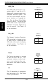
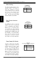
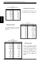
Extra Chassis Intrusion
Header
An additional chassis intrusion
header (the other is located on
JF1) is included on your mother-
board at JL1. If a chassis intru-
sion condition has been detected,
the mouse and keyboard will be
disabled (but no audible alarm will
be activated). All system opera-
tions will halt until the intrusion
microswitch is set back to normal.
See Table 2-22 for pin definitions.
Pin
Number
1
26
Definition
Intrusion Input
Ground
Table 2-22
Chassis Intrusion
Header Pin Definitions
(JL1)
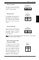
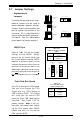
Power Supply Fail Header
Connect a cable from your power
supply to the header at JP12 to
provide warning of power supply
failure. This warning signal is
passed through the PWR_LED pin
on JL1 to provide indication of a
power failure on the chassis.
This feature is only available when
using Supermicro power supplies.
See Table 2-23 for pin definitions.
Table 2-23
Power Supply Fail Header Pin Definitions
(JP12)
Pin
Number
1
2
3
4
Definition
P/S 1 Fail Signal
P/S 2 Fail Signal
P/S 3 Fail Signal
Reset (from MB)