X7SPA-L X7SPA-H X7SPA-HF X7SPE-H X7SPE-HF X7SPE-H-D525 X7SPE-HF-D525 X7SPA-H-D525 X7SPA-HF-D525 USER’S MANUAL Revision 1.
The information in this User’s Manual has been carefully reviewed and is believed to be accurate. The vendor assumes no responsibility for any inaccuracies that may be contained in this document, makes no commitment to update or to keep current the information in this manual, or to notify any person or organization of the updates. Please Note: For the most up-to-date version of this manual, please see our web site at www.supermicro.com. Super Micro Computer, Inc.
Preface Preface About This Manual This manual is written for system integrators, PC technicians and knowledgeable PC users. It provides information for the installation and use of the X7SPA and X7SPE motherboard product series. This product is intended to be professionally installed and serviced by a technician.
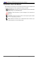
X7SPA and X7SPE Motherboard Series User’s Manual Conventions Used in the Manual: Special attention should be given to the following symbols for proper installation and to prevent damage done to the components or injury to yourself: Danger/Caution: Instructions to be strictly followed to prevent catastrophic system failure or to avoid bodily injury Warning: Critical information to prevent damage to the components or data loss.
Contacting Supermicro Contacting Supermicro Headquarters Address: Super Micro Computer, Inc. 980 Rock Ave. San Jose, CA 95131 U.S.A. Tel: +1 (408) 503-8000 Fax: +1 (408) 503-8008 Email: marketing@supermicro.com (General Information) support@supermicro.com (Technical Support) Web Site: www.supermicro.com Europe Address: Super Micro Computer B.V. Het Sterrenbeeld 28, 5215 ML 's-Hertogenbosch, The Netherlands Tel: +31 (0) 73-6400390 Fax: +31 (0) 73-6416525 Email: sales@supermicro.
X7SPA and X7SPE Motherboard Series User’s Manual Table of Contents Preface About This Manual......................................................................................................... iii About This Motherboard................................................................................................. iii Manual Organization...................................................................................................... iii Conventions Used in the Manual:............................
Table of Contents Slow Blinking LED for Suspend-State Indicator............................................ 1-24 BIOS Support for USB Keyboard.................................................................. 1-24 Main Switch Override Mechanism................................................................. 1-24 1-5 Power Supply................................................................................................. 1-24 1-6 Super I/O..............................................................
X7SPA and X7SPE Motherboard Series User’s Manual ATX Main PWR & CPU PWR Connectors . ............................................. 2-16 External Power Connector ....................................................................... 2-16 Fan Headers.............................................................................................. 2-17 Overheat/Fan Fail LED (JOH)................................................................... 2-18 Front Panel Audio Header (X7SPA-L Only)........................
Table of Contents Chapter 3 Troubleshooting 3-1 Troubleshooting Procedures............................................................................ 3-1 Before Power On............................................................................................. 3-1 No Power......................................................................................................... 3-1 No Video..........................................................................................................
X7SPA and X7SPE Motherboard Series User’s Manual Execute-Disable Bit Capability (Available when supported by the OS and the CPU)...................................................................................................... 4-6 Hyper-threading Technology........................................................................ 4-6 Advanced Chipset Control............................................................................ 4-7 Northbridge Configuration..........................................
Table of Contents Super IO Device Configuration .................................................................. 4-12 Serial Port1 Address/ Serial Port2 Address.............................................. 4-12 Remote Access Configuration . .................................................................. 4-13 Remote Access ........................................................................................ 4-13 Hardware Health Configuration.....................................................
X7SPA and X7SPE Motherboard Series User’s Manual Change Supervisor Password................................................................... 4-20 Change User Password............................................................................ 4-21 Boot Sector Virus Protection..................................................................... 4-21 4-5 Boot Settings................................................................................................. 4-22 Boot Device Priority.................
Chapter 1: Introduction Chapter 1 Introduction 1-1 Overview Checklist Congratulations on purchasing your computer motherboard from an acknowledged leader in the industry. Supermicro boards are designed with the utmost attention to detail and to provide you with the highest standards in quality and performance. Please check that the following items have all been included with your motherboard. If anything listed here is damaged or missing, contact your retailer.
X7SPA and X7SPE Motherboard Series User's Manual X7SPA-L Image Note: All graphics and images shown in this manual were based upon the latest PCB Revision available at the time of publishing of the manual. The motherboard you've received may or may not look exactly the same as the image shown in this manual.
Chapter 1: Introduction X7SPA-H Image Note: All graphics and images shown in this manual were based upon the latest PCB Revision available at the time of publishing of the manual. The motherboard you've received may or may not look exactly the same as the image shown in this manual.
X7SPA and X7SPE Motherboard Series User's Manual X7SPA-HF Image Note: All graphics shown in this manual were based upon the latest PCB Revision available at the time of publishing of the manual. The motherboard you've received may or may not look exactly the same as the graphics shown in this manual.
Chapter 1: Introduction X7SPE-H Image Note: All graphics shown in this manual were based upon the latest PCB Revision available at the time of publishing of the manual. The motherboard you've received may or may not look exactly the same as the graphics shown in this manual.
X7SPA and X7SPE Motherboard Series User's Manual X7SPE-HF Image Note: All graphics and images shown in this manual were based upon the latest PCB Revision available at the time of publishing of the manual. The motherboard you've received may or may not look exactly the same as the image shown in this manual.
Chapter 1: Introduction X7SPE-H-D525 Image Note: All graphics and images shown in this manual were based upon the latest PCB Revision available at the time of publishing of the manual. The motherboard you've received may or may not look exactly the same as the image shown in this manual.
X7SPA and X7SPE Motherboard Series User's Manual X7SPE-HF-D525 Image Note: All graphics and images shown in this manual were based upon the latest PCB Revision available at the time of publishing of the manual. The motherboard you've received may or may not look exactly the same as the image shown in this manual.
Chapter 1: Introduction X7SPA-H-D525 Image Note: All graphics and images shown in this manual were based upon the latest PCB Revision available at the time of publishing of the manual. The motherboard you've received may or may not look exactly the same as the image shown in this manual.
X7SPA and X7SPE Motherboard Series User's Manual X7SPA-HF-D525 Image Note: All graphics and images shown in this manual were based upon the latest PCB Revision available at the time of publishing of the manual. The motherboard you've received may or may not look exactly the same as the image shown in this manual.
Chapter 1: Introduction JSMB1:SMBus1 JPW1 MH3 KB/MOUSE CPU FAN MH2 Motherboard Layout (X7SPA-L, X7SPA-H, X7SPA-HF, X7SPA-H-D525, X7SPA-HF-D525) JSMB1 FAN1 JLPC80 FAN2 J14 JPI2C:PWR I2C JPG1:VGA 1-2 ENABLE 2-3 DISABLE JI2C2 JD1:1-3 PWR LED 4-7 SPEAKER JWD1:1-2 RST 2-3 NMI JWF1:DOM PWR JWF1 J3 T-SGPIO2 T-SGPIO1 J2 I-SATA1 I-SATA2 I-SATA0 JWD1 JBT1 +SP1 SODIMM1 SODIMM2 JBT1: COMS CLEAR JPC3 JD1 JF1 PWR ON RST X OH/FF NIC2 NIC1 HDD LED PWR LED X NMI JL1:CHASISS INTRUSION JPB:BMC
X7SPA and X7SPE Motherboard Series User's Manual JSMB1:SMBus1 JPW1 MH3 KB/MOUSE CPU FAN MH2 Motherboard Layout (X7SPE-H, X7SPE-HF, X7SPE-H-D525, X7SPE-HF-D525) JSMB1 FAN1 JLPC80 FAN2 JPI2C:PWR I2C JPG1:VGA 1-2 ENABLE 2-3 DISABLE JD1 JWD1:1-2 RST 2-3 NMI JWF1:DOM PWR JWF1 J3 T-SGPIO2 T-SGPIO1 J2 I-SATA1 I-SATA2 I-SATA0 JWD1 JI2C2 JD1:1-3 PWR LED 4-7 SPEAKER JPT1:TPM ENABLE/DISABLE 1-2 ENABLE 2-3 DISABLE JPL1:1-2 ENABLE 2-3 DISABLE JPL2:1-2 ENABLE 2-3 DISABLE JL1:CHASISS INTRUSION JP
Chapter 1: Introduction X7SPA-L, X7SPA-H, X7SPA-HF, X7SPA-H-D525, X7SPAHF-D525 Quick Reference (not drawn to scale) JSMB1:SMBus1 JPW1 JSMB1 FAN1 JLPC80 FAN2 SYS FAN J6 50 J5 JPF J14 JPI2C:PWR I2C JPG1:VGA 1-2 ENABLE 2-3 DISABLE JI2C2 JD1 32 JWD1:1-2 RST 2-3 NMI JWF1:DOM PWR 30 JWF1 T-SGPIO2 T-SGPIO1 J2 I-SATA1 I-SATA2 I-SATA0 28 JWD1 +SP1 33 JD1:1-3 PWR LED 4-7 SPEAKER JPT1:TPM ENABLE/DISABLE 1-2 ENABLE 2-3 DISABLE JPL1:1-2 ENABLE 2-3 DISABLE JPL2:1-2 ENABLE 2-3 DISABLE JBT1 4
X7SPA and X7SPE Motherboard Series User's Manual X7SPE-H/X7SPE-HF, X7SPE-H-D525, X7SPE-HF-D525, Quick Reference 1 34 JSMB1:SMBus1 JPW1 JSMB1 FAN1 50 6 JI2C2 JPI2C:PWR I2C JPG1:VGA 1-2 ENABLE 2-3 DISABLE JD1 32 JD1:1-3 PWR LED 4-7 SPEAKER JL1:CHASISS INTRUSION 33 JWD1:1-2 RST 2-3 NMI JWF1:DOM PWR 30 JWF1 J3 T-SGPIO2 T-SGPIO1 J2 I-SATA1 I-SATA2 I-SATA0 28 JWD1 +SP1 SODIMM1 SODIMM2 JBT1: COMS CLEAR JBT1 JVGA1 JPB:BMC ENABLE/DISABLE 1-2 ENABLE 2-3 DISABLE JL2:AUDIO FRONT PANEL S
Chapter 1: Introduction Ports and Connectors Number Connectors Description 1 2, 3 4 KB/Mouse USB 1/2, USB 3/4 COM1 5 6 VGA LAN1 PS/2 Keyboard/Mouse Back Panel USB Ports (USB 3/4: X7SPA-L only) Back Panel Serial Port Video/Graphics Connector 7 LAN2 8 J5 10 CD1 15 18 JL1 JBAT1 19 JPCIE1 20 21 22 23 25 USB 5/6, 7/8 JTPM USB 10 USB 9 JOH 26 J8 27 29 30 31 SATA 0,1,2,3,4,5 JWF1 T-SGPIO-0/1 JF1 32 JD1 33 34 35 36 38, 37 JPI2C JPW1 Unused JSMB1 Fans 1, 2 COM2, COM4, COM3 SPK J5 J6 DIMM 1
X7SPA and X7SPE Motherboard Series User's Manual Jumper Descriptions Number Jumper Description AC97/HD Audio Selector (Front Panel) SMB to PCI Slots LAN2 Enable/Disable LAN1 Enable/Disable 9 JL2 12, 11 13 14 JI2C1/JI2C2 JPL2 JPL1 16 JPG1 17 JPB 24 28 JPUSB1 JWD1 BMC Enable/Disable (X7SPA-HF, X7SPE-HF, and X7SPE-HF-D525 only) USB Wake-up Enable Watch Dog Timer 42 JPT1 Trusted Platform Module Enable 43 JPC3 44 JBT1 46 J12/J13 47 J10/J11 52 53 JPF J14 On-board VGA Enable/Disable (X7S
Chapter 1: Introduction Features Model CPU X7SPA-L X7SPA-H X7SPA-HF X7SPE-H X7SPE-HF X7SPE-H-D525 X7SPE-HF-D525 X7SPA-H-D525 X7SPA-HF-D525 Intel ATOM D410 Intel ATOM D510 Intel ATOM D510 Intel ATOM D510 Intel ATOM D510 Intel ATOM D525 Intel ATOM D525 Intel ATOM D525 Intel ATOM D525 Model USB VGA Graphics Intel Graphics Media Accelerator GMA3150 Intel Graphics Media Accelerator GMA3150 Matrox G200eW Graphics Accelerator Intel Graphics Media Accelerator GMA3150 Matrox G200eW Graphics Accelerator Intel
X7SPA and X7SPE Motherboard Series User's Manual Motherboard Features Processor X7SPA-L Single Integrated Intel® ATOM™ D410 processor, 1.66 GHz, 10 Watts, 512KB L2 cache, Single Core, Dual Threads. X7SPA-H, X7SPA-HF, X7SPE-H, X7SPE-HF Single Integrated Dual-Core Intel® ATOM™ D510 processor, 1.66 GHz, 13 Watts, 2 x 512KB L2 cache, Dual Core, 4 Threads. X7SPE-H-D525, X7SPE-HF-D525, X7SPA-H-D525, X7SPA-HF-D525 Single Integrated Dual-Core Intel® ATOM™ D525 processor, 1.
Chapter 1: Introduction PC Health Monitoring Onboard voltage monitors for CPU Cores, Chipset Voltage, Memory Voltage +1.8V, +3.3V, +5V, +/- 12V, +3.
X7SPA and X7SPE Motherboard Series User's Manual X7SPA-H/X7SPE-H/X7SPE-H-D525/X7SPA-H-D525 Only 6 SATA connectors for 6 devices • • • • RAID support: RAID 0, 1, 5, 10 (Windows OS), RAID 0, 1, 10 (Linux OS) Dual 10/100/1000 LAN (Intel 82574L) Two Fast UART 16550-compatible serial ports (one back panel, one header) • Eight (8) USB 2.0 ports & headers (USB1/2, USB5~10): Two ports on the back panel, five USB headers for front panel access, and one on-board Type A USB port.
Chapter 1: Introduction X7SPA-H/X7SPA-HF/ X7SPE-H/X7SPE-HF/ X7SPE-H-D525/X7SPE-HF-D525 Only LVDS Connector SATA Port 4 SATA Port 3 SATA Port 5 SATA Port 2 SATA Port 6 SATA Port 1 USB Vertical CONN x1 USB Headerx3 (5Ports) *x4 X7SPA-L Only USB *x4/x2 Rear CONN DDR2 667 Intel ATOM *D410/D510/D525 *SC/DC DDR3 800 (X7SPE-H-D525, X7SPE-HF-D525, X7SPA-H-D525, X7SPA-HF-D525) 12V DC PSU 4-PIN CONN ATX PSU 24PIN CONN DMI SATA GEN2 *x4/x6 Intel USB 2.
X7SPA and X7SPE Motherboard Series User's Manual 1-2 Chipset Overview I/O Controller Hub: ICH9R (X7SPA-H/X7SPA-HF, X7SPE-H/ X7SPE-HF, X7SPE-H-D525, X7SPE-HF-D525, X7SPAH-D525, X7SPA-HF-D525) The I/O Controller ICH9R provides the data buffering and interface arbitration required for the system to operate efficiently. It also provides the bandwidth needed for the system to maintain its peak performance. The Direct Media Interface (DMI) provides the connection between the MCH and the ICH9R.
Chapter 1: Introduction 1-3 PC Health Monitoring This section describes the PC health monitoring features of the X7SPA and X7SPE series. The motherboard has an onboard System Hardware Monitor chip that supports PC health monitoring. Recovery from AC Power Loss BIOS provides a setting for you to determine how the system will respond when AC power is lost and then restored to the system.
X7SPA and X7SPE Motherboard Series User's Manual 1-4 Power Configuration Settings This section describes features of your motherboard that deal with power and power settings. Slow Blinking LED for Suspend-State Indicator When the CPU goes into a suspend state, the chassis power LED will start blinking to indicate that the CPU is in suspend mode. When the user presses any key, the CPU will wake up and the LED will automatically stop blinking and remain on.
Chapter 1: Introduction 1-6 Super I/O The Super I/O provides two high-speed, 16550 compatible serial communication ports (UARTs). Each UART includes a 16-byte send/receive FIFO, a programmable baud rate generator, complete modem control capability and a processor interrupt system. Both UARTs provide legacy speed with baud rate of up to 115.2 Kbps as well as an advanced speed with baud rates of 250 K, 500 K, or 1 Mb/s, which support higher speed modems.
X7SPA and X7SPE Motherboard Series User's Manual 1-8 LVDS (X7SPA-L only) Low-Voltage Differential Signaling (LVDS) is an industry-standard electrical signaling system. This signaling system can run at very high speeds over inexpensive copper wires using low power. The LVDS bus on the X7SPA-L motherboard is used to transport video data from the built-in graphics adapter to a computer monitor, such as a user-supplied external LCD display.
Chapter 2: Installation Chapter 2 Installation 2-1 Static-Sensitive Devices Electrostatic-Discharge (ESD) can damage electronic components. To prevent damage to your system board, it is important to handle it very carefully. The following measures are generally sufficient to protect your equipment from ESD. Precautions • Use a grounded wrist strap designed to prevent static discharge. • Touch a grounded metal object before removing the board from the antistatic bag.
X7SPA and X7SPE Motherboard Series User's Manual 2-2 Motherboard Installation All motherboards have standard mounting holes to fit different types of chassis. Make sure that the locations of all the mounting holes for both motherboard and chassis match. Although a chassis may have both plastic and metal mounting fasteners, metal ones are highly recommended because they ground the motherboard to the chassis. Make sure that the metal standoffs click in or are screwed in tightly.
Chapter 2: Installation Caution: To avoid damaging the motherboard and its components, please do not use a force greater than 8 lb/inch on each mounting screw during motherboard installation. Installation Instructions 1 Install the I/O shield into the chassis. I/O Shield 2 3 Locate the mounting holes on the motherboard. Refer to the layout on the previous page for mounting hole locations. Locate the matching mounting holes on the chassis. Install standoffs in the chassis as needed.
X7SPA and X7SPE Motherboard Series User's Manual 2-3 System Memory CAUTION Exercise extreme care when installing or removing DIMM modules to prevent any possible damage. Note: Check the Supermicro website for a list of memory modules that have been validated with the X7SPA and X7SPE motherboard series. How to Install SO DIMMs 1. Insert the desired number of SO DIMMs into the memory slots, starting with DIMM1, then DIMM2.
Chapter 2: Installation The SO DIMM Socket Align 1 Position the SO DIMM module's bottom key so it aligns with the receptive point on the slot. 2 Insert the SO DIMM module vertically at about a 45 degree angle. Insert this end first 3 4 Press down until the module locks into place. The side clips will automatically secure the SO DIMM module, locking it into place. Press down until the module locks into place.
X7SPA and X7SPE Motherboard Series User's Manual 2-4 Connectors/I/O Ports The I/O ports are color coded in conformance with the PC 99 specification. See the figure below for the colors and locations of the various I/O ports.
Chapter 2: Installation ATX PS/2 Keyboard and PS/2 Mouse Ports PS/2 Keyboard/Mouse Pin Definitions The ATX PS/2 keyboard and PS/2 mouse are located next to the Back Panel USB Ports 0/1 on the motherboard. See the table at right for pin definitions.
X7SPA and X7SPE Motherboard Series User's Manual Universal Serial Bus (USB) Back Panel USB 1/2/3/4, Type A USB 10 Pin Definitions Four Universal Serial Bus ports (USB 1/2/3/4) are located on the I/O backpanel. Additionally, one Type A Internal USB port (USB 10) and five USB headers (USB 5/6, 7/8, 9) are also located on the motherboard to provide front chassis access. (Cables are not included). See the tables on the right for pin definitions.
Chapter 2: Installation Serial Ports Serial Ports-COM1/COM2/COM3/COM4 Pin Definitions Two COM connections (COM1, COM2) are located on the motherboard. COM1 is located on the back I/O panel. COM2 is located just behind the back panel connectors to provide additional onboard serial connection support. See the table on the right for pin definitions.
X7SPA and X7SPE Motherboard Series User's Manual VGA Connector A VGA connector is located next to the COM1 Port on the I/O back panel. This connector is used to provide video display. Refer to the board layout below for the location.
Chapter 2: Installation LAN Ports / IPMI RJ45/LAN Pin Definitions LAN ports are located on the I/O back panel. These ports accept RJ45 type cables.
X7SPA and X7SPE Motherboard Series User's Manual Front Control Panel JF1 contains header pins for various buttons and indicators that are normally located on a control panel at the front of the chassis. These connectors are designed specifically for use with Supermicro server chassis. See the figure below for the descriptions of the various control panel buttons and LED indicators. Refer to the following section for descriptions and pin definitions.
Chapter 2: Installation Front Control Panel Pin Definitions Power LED Power LED Pin Definitions (JF1) The Power LED connection is located on pins 15 and 16 of JF1. Refer to the table on the right for pin definitions. Pin# Definition 15 +3.3V 16 Ground HDD LED The HDD LED connection is located on pins 13 and 14 of JF1. Attach a hard drive LED cable here to display disk activity (for any hard drive activities on the system, including Serial ATA and IDE).
X7SPA and X7SPE Motherboard Series User's Manual Overheat (OH)/Fan Fail LED OH/Fan Fail LED Pin Definitions (JF1) Connect an LED Cable to the OH/ Fan Fail connection on pins 7 and 8 of JF1 to provide advanced warnings of chassis overheat or fan failure. Refer to the table on the right for pin definitions.
Chapter 2: Installation Reset Button Reset Button Pin Definitions (JF1) The Reset Button connection is located on pins 3 and 4 of JF1. Attach it to a hardware reset switch on the computer case. Refer to the table on the right for pin definitions. The Power Button connection is located on pins 1 and 2 of JF1. Momentarily contacting both pins will power on/off the system. To turn off the power when set to suspend mode, press the button for at least 4 seconds.
X7SPA and X7SPE Motherboard Series User's Manual 2-5 Connecting Cables This section provides brief descriptions and pin-out definitions for onboard power connectors. Be sure to use the correct cable for each header or connector. ATX Main PWR & CPU PWR Connectors ATX Power 24-pin Connector Pin Definitions (JPW1) The 24-pin main power connector (JPW1) is used to provide power to the motherboard. This connector meets the SSI EPS 12V specification. See the table on the right for pin definitions.
Chapter 2: Installation Fan Headers The X7SPA and X7SPE series has two fan headers. Fan1 is the CPU fan and Fan2 is for the system cooling fan. These fans are 4-pin fan headers. However, Pins 1~3 of the fan headers are backward compatible with the traditional 3-pin fans. (Note: Please use all 3-pin fans or all 4-pin fans on a motherboard. Please do not use 3-pin fans and 4-pin fans on the same board. Refer to the table on the right for pin definitions.
X7SPA and X7SPE Motherboard Series User's Manual Overheat/Fan Fail LED (JOH) Overheat LED Pin Definitions The JOH header is used to connect an LED to provide warnings of chassis overheat. This LED will also blink to indicate a fan failure. Refer to the table on right for pin definitions.
Chapter 2: Installation Chassis Intrusion A Chassis Intrusion header is located at JL1 on the motherboard. Attach the appropriate cable from the chassis to inform you of a chassis intrusion when the chassis is opened. Chassis Intrusion Pin Definitions (JL1) Pin# Definition 1 Intrusion Input 2 Ground SATA DOM Power The SATA DOM Power on JWF1 is used to supply power to SATA Disk-on-Module (DOM) solid-state storage devices.
X7SPA and X7SPE Motherboard Series User's Manual CD Header (X7SPA-L Only) CD Header Pin Definitions A 4-pin CD header located at CD1 is available on the X7SPA-L. This header allows you to use the onboard sound for audio CD playback. Connect an audio cable from your CD drive to the header that fits your cable's connector. See the table at right for pin definitions.
Chapter 2: Installation LVDS Connector (X7SPA-L Only) An LVDS connector (J5) is available on the X7SPA-L only. This connector provides 18-bit LVDS (Low Voltage Differential Signaling) for an LCD panel or other similar devices. Refer to the table on the right for pin definitions. Inverter Power Connector (X7SPA-L Only) The inverter connector on J6 is a 7-pin connector and is used in conjunction with the LVDS connector. Connect the backlight module of the LCD panel to this socket.
X7SPA and X7SPE Motherboard Series User's Manual TPM Header (X7SPE-H-D525, X7SPE-HF-D525 Only) Trusted Platform Module Header Pin Definitions Pin # This header is used to connect a Trusted Platform Module (TPM), available from a third-party vendor. A TPM is a security device that allows encryption and authentication of hard drives. It enables the motherboard to deny access if the TPM associated with the hard drive is not installed in the system. See the table on the right for pin definitions.
Chapter 2: Installation 2-6 Jumper Settings Explanation of Jumpers To modify the operation of the motherboard, jumpers can be used to choose between optional settings. Jumpers create shorts between two pins to change the function of the connector. Pin 1 is identified with a square solder pad on the printed circuit board. Note: On two pin jumpers, "Closed" means the jumper is on and "Open" means the jumper is off the pins.
X7SPA and X7SPE Motherboard Series User's Manual LAN Port Enable/Disable GLAN Enable Jumper Settings JPL1/JPL2 enable or disable LAN Port 1/LAN Port 2 on the motherboard. See the table on the right for jumper settings. The default setting is enabled. Pin# Definition 1-2 Enabled (default) 2-3 Disabled Note: LAN Port 2 is not available on the X7SPA-L.
JPT1 JI2C2 T-SGPIO1 Motherboard AUDIO FP Important: For an ATX power supply, you must completely shut down the system, remove the AC power cord and then short JBT1 to clear CD-in CMOS.
X7SPA and X7SPE Motherboard Series User's Manual USB Wake-Up (Not Available on the X7SPE-H-D525, X7SPA-H-D525, X7SPAHF-D525 and X7SPE-HF-D525) USB Wake-Up Jumper Settings Jumper Setting Use JPUSB jumper to enable the function of "System Waking-Up via USB devices". This jumper allows you to "wake-up" the system by pressing a key on the USB keyboard or by clicking the USB mouse of your system. The JPUSB jumper is used together with the USB Wake-Up function in the BIOS.
Chapter 2: Installation TPM Support Enable (Not available on X7SPA-H-D525, X7SPA-HF-D525, X7SPE-H-D525, X7SPE-HF-D525) TPM Support Enable Jumper Settings Jumper Setting JPT1 allows the user to enable TPM (Trusted Platform Modules) support to enhance data integrity and system security. See the table on the right for jumper settings. The default setting is enabled.
X7SPA and X7SPE Motherboard Series User's Manual Power LED/Speaker On the JD1 header, pins 1~3 are used for a power LED and pins 4~7 are used for an external speaker. If you wish to use the onboard speaker, you should close pins 6-7 with a jumper. See the table on the right for speaker pin definitions.
Chapter 2: Installation VGA Enable (X7SPA-HF, X7SPE-HF, X7SPE-HF-D525, X7SPA-HF-D525 only) VGA Enable Jumper Settings JPG1 allows the user to enable or disable the onboard VGA adapter on the X7SPA-HF, X7SPE-HF, X7SPA-HF-D525 and X7SPEHF-D525. The default setting is Enabled. Pin# Definition 1-2 Enabled (default) 2-3 Disabled HDA/AC97 Select (X7SPA-L Only) HDA/AC97 Jumper Settings JL2 allows the user to select between High Definition Audio (HDA) or legacy AC97 audio.
X7SPA and X7SPE Motherboard Series User's Manual Power Force On Enable/Disable Power Force On Enable/Disable Jumper Settings Jumper JPF allows you to enable (force on) or disable the Power Force On function. If enabled, the power will always stay on automatically. If this function is disabled (the normal setting), the user needs to press the power button to power on the system.
Chapter 2: Installation Onboard Indicators GLAN Link/Speed LED Indicator LAN Port LEDs Two LAN ports are located on the I/O Backplane. Each Ethernet LAN port has two LEDs. The yellow Activity LED (right, see below) indicates activity, while the Link/ Speed LED (left) may be green, amber or off to indicate the speed of the connection. See the tables at right for more information.
X7SPA and X7SPE Motherboard Series User's Manual 2-8 Serial ATA and HDD Connections Note the following conditions when connecting the Serial ATA and hard disk drive cables: • Be sure to use the correct cable for each connector. Refer to Page 1-1 for cables that came with your shipment. SATA Connectors SATA Connectors Pin Definitions Six (6) Serial ATA (SATA) connectors (I-SATA 0~5) are located on the motherboard, to provide serial link connections.
Chapter 3: Troubleshooting Chapter 3 Troubleshooting 3-1 Troubleshooting Procedures Use the following procedures to troubleshoot your system. If you have followed all of the procedures below and still need assistance, refer to the ‘Technical Support Procedures’ and/or ‘Returning Merchandise for Service’ section(s) in this chapter. Always disconnect the AC power cord before adding, changing or installing any hardware components. Before Power On 1.
X7SPA and X7SPE Motherboard Series User's Manual 2. Use the speaker to determine if any beep codes exist. (Refer to Appendix A for details on beep codes.) 3. Remove all memory modules and turn on the system. (If the alarm is on, check the specs of memory modules, reset the memory or try a different one.) Memory Errors 1. Make sure that the SO-DIMM modules are properly installed and fully seated in the slots. 2. Please check Section 2-3 and make sure that you are using the correct memory.
Chapter 3: Troubleshooting Note: Not all BIOS can be flashed. Some cannot be flashed; it depends on the modifications to the boot block code. 3.
X7SPA and X7SPE Motherboard Series User's Manual Question: How do I update my BIOS? Answer: It is recommended that you do not upgrade your BIOS if you are not experiencing any problems with your system. Updated BIOS files are located on our web site at http://www.supermicro.com/support/bios/. Please check our BIOS warning message and the information on how to update your BIOS on our web site. Select your motherboard model and download the BIOS (.rom) file to your computer.
Chapter 3: Troubleshooting 3-4 Returning Merchandise for Service A receipt or copy of your invoice marked with the date of purchase is required before any warranty service will be rendered. You can obtain service by calling your vendor for a Returned Merchandise Authorization (RMA) number. When returning to the manufacturer, the RMA number should be prominently displayed on the outside of the shipping carton, and mailed prepaid or hand-carried.
X7SPA and X7SPE Motherboard Series User's Manual Notes 3-6
Chapter 4: AMI BIOS Chapter 4 BIOS 4-1 Introduction This chapter describes the AMI BIOS Setup Utility for the X7SPA and X7SPE series. The AMI ROM BIOS is stored in a Flash EEPROM and can be easily updated. This chapter describes the basic navigation of the AMI BIOS Setup Utility setup screens. Note: For instructions on BIOS recovery, please refer to the instruction guide posted at http://www.supermicro.com/support/manuals/.
X7SPA and X7SPE Motherboard Series User's Manual How to Start the Setup Utility Normally, the only visible Power-On Self-Test (POST) routine is the memory test. As the memory is being tested, press the key to enter the main menu of the AMI BIOS Setup Utility. From the main menu, you can access the other setup screens. An AMI BIOS identification string is displayed at the left bottom corner of the screen, below the copyright message.
Chapter 4: AMI BIOS System Overview: The following BIOS information will be displayed: System Time/System Date Use this option to change the system time and date. Highlight System Time or System Date using the arrow keys. Enter new values through the keyboard. Press the key or the arrow keys to move between fields. The date must be entered in Day MM/DD/YY format. The time is entered in HH:MM:SS format. (Note: The time is in the 24-hour format. For example, 5:30 P.M. appears as 17:30:00.
X7SPA and X7SPE Motherboard Series User's Manual 4-3 Advanced Setup Configurations Use the arrow keys to select Boot Setup and hit to access the submenu items: BOOT Feature Quick Boot If Enabled, this option will skip certain tests during POST to reduce the time needed for system boot. The options are Enabled and Disabled. Quiet Boot This option allows the bootup screen options to be modified between POST messages or the OEM logo. Select Disabled to display the POST messages.
Chapter 4: AMI BIOS Bootup Num-Lock This feature selects the Power-on state for Numlock key. The options are Off and On. PS/2 Mouse Support This feature enables support for the PS/2 mouse. The options are Disabled, Enabled and Auto. Wait For 'F1' If Error This forces the system to wait until the 'F1' key is pressed if an error occurs. The options are Disabled and Enabled. Hit 'Del' Message Display This feature displays "Press DEL to run Setup" during POST. The options are Enabled and Disabled.
X7SPA and X7SPE Motherboard Series User's Manual Standby Power in S5 This feature supplies standby power while in S5 (sleep mode). Set this feature to Disabled to comply with EuP requirements, Enable this feature to activate wake-up capability while in sleep mode. The options are Enabled and Disabled. CPU Configuration Warning: Take Caution when changing the Advanced settings. An incorrect value, a very high DRAM frequency or incorrect DRAM timing may cause system to become unstable.
Chapter 4: AMI BIOS Advanced Chipset Control The items included in the Advanced Settings submenu are listed below. Northbridge Configuration DRAM Frequency This option allows the user to select the desired frequency setting for the onboard memory modules. The options are Auto, 667 MHz and 800 MHz. (667 MHz is not available on the X7SPE-H-D525, X7SPA-HF-D525 and X7SPE-HF-D525). Configure DRAM Timing by SPD This option allows the user to select the desired DRAM timing for the onboard memory modules.
X7SPA and X7SPE Motherboard Series User's Manual Video Function Configuration (X7SPA-L, X7SPE-H, X7SPA-H-D525 and X7SPE-H-D525 only) DVMT Mode Select Select DVMT Mode to enable Dynamic Video Memory Technology (DVMT). The options are Fixed Mode and DVMT Mode. DVMT/Fixed Memory This item selects the DVMT/Fixed memory size. The options are 128MB, 256MB and Maximum DVMT. Boot Display Device This item selects the display device the motherboard uses during system boot. The options are CRT, LVDS and CRT + LVDS.
Chapter 4: AMI BIOS on the motherboard, and vise versa. The settings are Disabled, Enabled and Auto. USB Controller This feature allows the user to Enable or Disable the onboard USB controller. The options are Enabled and Disabled. Note: This function is grayed-out if USB Functions above is set to Enabled.
X7SPA and X7SPE Motherboard Series User's Manual LBA/Large Mode LBA (Logical Block Addressing) is a method of addressing data on a disk drive. In the LBA mode, the maximum drive capacity is 137 GB. For drive capacities over 137 GB, your system must be equipped with a 48-bit LBA mode addressing. If not, contact your manufacturer or install an ATA/133 IDE controller card that supports 48-bit LBA mode. The options are Disabled and Auto.
Chapter 4: AMI BIOS Select SWDMA2 to allow the BIOS to use Single Word DMA mode 2. It has a data transfer rate of 8.3 MBs. Select MWDMA0 to allow the BIOS to use Multi Word DMA mode 0. It has a data transfer rate of 4.2 MBs. Select MWDMA1 to allow the BIOS to use Multi Word DMA mode 1. It has a data transfer rate of 13.3 MBs. Select MWDMA2 to allow the BIOS to use Multi-Word DMA mode 2. It has a data transfer rate of 16.6 MBs. Select UDMA0 to allow the BIOS to use Ultra DMA mode 0.
X7SPA and X7SPE Motherboard Series User's Manual Plug & Play OS Selecting Yes allows the OS to configure Plug & Play devices. (This is not required for system boot if your system has an OS that supports Plug & Play.) Select No to allow the AMI BIOS to configure all devices in the system. PCI Latency Timer This feature sets the latency Timer of each PCI device installed on a PCI bus. Select 64 to set the PCI latency to 64 PCI clock cycles. The options are 32, 64, 96, 128, 160, 192, 224 and 248.
Chapter 4: AMI BIOS for Serial Port1 are Disabled, 3F8/IRQ4, 2E8/IRQ3. The options for Serial Port2 are Disabled, 2F8/IRQ3, and 2E8/IRQ3. Remote Access Configuration Remote Access This allows the user to enable the Remote Access feature. The options are Disabled and Enabled. If Remote Access is set to Enabled, the following items will display: Serial Port Number This feature allows the user decide which serial port to be used for Console Redirection. The options are COM 1, COM 2 and COM 3.
X7SPA and X7SPE Motherboard Series User's Manual Hardware Health Configuration This feature allows the user to monitor Hardware Health of the system and review the status of each item when displayed. CPU Overheat Alarm This option allows the user to select the CPU Overheat Alarm setting which determines when the CPU OH alarm will be activated to provide warning of possible CPU overheat.
Chapter 4: AMI BIOS User intervention: No action is required. However, consider checking the CPU fans and the chassis ventilation for blockage. High – The processor is running hot. This is a ‘caution’ level since the CPU’s ‘Temperature Tolerance’ has been reached (or has been exceeded) and may activate an overheat alarm: The Default Alarm – the Overheat LED and system buzzer will activate if the High condition continues for some time after it is reached.
X7SPA and X7SPE Motherboard Series User's Manual Fan Speed Control Modes This feature allows the user to decide how the system controls the speeds of the onboard fans. The CPU temperature and the fan speed are correlative. When the CPU on-die temperature increases, the fan speed will also increase for effective system cooling. Select Full Speed to allow the onboard fans to run at full speed (of 100% Pulse Width Modulation Duty Cycle) for maximum cooling.
Chapter 4: AMI BIOS ACPI Aware O/S Enable ACPI support if it is supported by the OS to control ACPI through the Operating System. Otherwise, disable this feature. The options are Yes and No. Suspend Mode This setting allows you to configure the ACPI (Advanced Configuration and Power Interface) state for your system when it is in the Suspend mode. The options are S1, S3 and Auto.
X7SPA and X7SPE Motherboard Series User's Manual Status of BMC Baseboard Management Controller (BMC) manages the interface between system management software and platform hardware. This is an informational feature which returns the status code of the BMC micro controller. IPMI Function Set this item to Disabled to turn off the IPMI feature. The options are Enabled and Disabled.. View BMC System Event Log This feature is used to view any BMC events.
Chapter 4: AMI BIOS Gateway Address - Enter the Gateway address this machine will use (i.e., 192.168.10.1). MAC Address - The BIOS will automatically enter the MAC address (also known as Hardware Address) of this machine, however it may be over-ridden. MAC addresses are 6 two-digit hexadecimal numbers (Base 16, 0 ~ 9, A, B, C, D, E, F) separated by dots. (i.e., 00.30.48.D0.D4.60) BMC Watch Dog Timer Action Allows the BMC to reset or power down the system if the operating system hangs or crashes.
X7SPA and X7SPE Motherboard Series User's Manual 4-4 Security Settings The AMI BIOS provides a Supervisor and a User password. If you use both passwords, the Supervisor password must be set first. Supervisor Password This item indicates if a supervisor password has been entered for the system. Clear means such a password has not been used and Set means a supervisor password has been entered for the system. User Password: This item indicates if a user password has been entered for the system.
Chapter 4: AMI BIOS Change User Password Select this feature and press to access the submenu , and then type in a new User Password. Clear User Password (Available only if User Password has been set) Password Check Available options are Setup and Always. Boot Sector Virus Protection When Enabled, the AMI BOIS displays a warning when any program (or virus) issues a Disk Format command or attempts to write to the boot sector of the hard disk drive. The options are Enabled and Disabled.
X7SPA and X7SPE Motherboard Series User's Manual 4-5 Boot Settings Use this feature to configure Boot Settings: Boot Device Priority This feature allows the user to specify the sequence of priority for the Boot Device. The settings are 1st boot device, 2nd boot device, 3rd boot device, 4th boot device, 5th boot device and Disabled.
Chapter 4: AMI BIOS Removable Drives This feature allows the user to specify the boot sequence from available Removable Drives. The settings are 1st boot device, 2nd boot device, and Disabled. • 1st Drive • 2nd Drive - [USB: XXXXXXXXX] Retry Boot Devices Select this option to retry booting from the configured boot devices if the systems fail to boot initially. The options are Disabled and Enabled.
X7SPA and X7SPE Motherboard Series User's Manual figuration parameters can take effect. Select Save Changes and Exit from the Exit menu and press . Discard Changes and Exit Select this option to quit the BIOS Setup without making any permanent changes to the system configuration, and reboot the computer. Select Discard Changes and Exit from the Exit menu and press . Discard Changes Select this option and press to discard all the changes and return to the AMI BIOS Utility Program.
Appendix A: POST Error Beep Codes Appendix A POST Error Beep Codes This section lists POST (Power On Self Test) error beep codes for the AMI BIOS. POST error beep codes are divided into two categories: recoverable and terminal. This section lists Beep Codes for recoverable POST errors. Recoverable POST Error Beep Codes When a recoverable type of error occurs during POST, BIOS will display a POST code that describes the problem.
X7SPA and X7SPE Motherboard Series User's Manual Notes A-2
Appendix C: Software Installation Instructions Appendix B Software Installation Instructions B-1 Installing Drivers After you've installed the Windows Operating System, a screen as shown below will appear. You are ready to install software programs and drivers that have not yet been installed. To install these software programs and drivers, click the icons to the right of these items.
X7SPA and X7SPE Motherboard Series User's Manual B-2 Configuring Supero Doctor III The Supero Doctor III program is a Web-base management tool that supports remote management capability. It includes Remote and Local Management tools. The local management is called the SD III Client. The Supero Doctor III program included on the CDROM that came with your motherboard allows you to monitor the environment and operations of your system.
Appendix C: Software Installation Instructions Supero Doctor III Interface Display Screen-II (Remote Control) Note: SD III Software Revision 1.0 can be downloaded from our Web site at: ftp://ftp.supermicro.com/utility/Supero_Doctor_III/. You can also download SDIII User's Guide at: http://www.supermicro.com/PRODUCT/ Manuals/SDIII/UserGuide.pdf. For Linux, we will still recommend that you use Supero Doctor II.
X7SPA and X7SPE Motherboard Series User's Manual Notes B-4
Disclaimer The products sold by Supermicro are not intended for and will not be used in life support systems, medical equipment, nuclear facilities or systems, aircraft, aircraft devices, aircraft/emergency communication devices or other critical systems whose failure to perform be reasonably expected to result in significant injury or loss of life or catastrophic property damage.