SUPER ® SUPERSERVER 5014C-T USER’S MANUAL Revision 1.
The information in this User’s Manual has been carefully reviewed and is believed to be accurate. The vendor assumes no responsibility for any inaccuracies that may be contained in this document, makes no commitment to update or to keep current the information in this manual, or to notify any person or organization of the updates. Please Note: For the most up-to-date version of this manual, please see our web site at www.supermicro.com.
Preface Preface About This Manual This manual is written for professional system integrators and PC technicians. It provides information for the installation and use of the SuperServer 5014C-T. Installation and maintainance should be performed by experienced technicians only. The SuperServer 5014C-T is a high-end single processor 1U rackmount server based on the SC811T-260 server chassis and the Super P8SCi motherboard.
SUPERSERVER 5014C-T User's Manual Chapter 4: System Safety You should thoroughly familiarize yourself with this chapter for a general overview of safety precautions that should be followed when installing and servicing the SuperServer 5014C-T. Chapter 5: Advanced Motherboard Setup Chapter 5 provides detailed information on the P8SCi motherboard, including the locations and functions of connectors, headers and jumpers.
Preface Notes v
SUPERSERVER 5014C-T User's Manual Table of Contents Preface About This Manual ...................................................................................................... iii Manual Organization ................................................................................................... iii Chapter 1: Introduction 1-1 Overview ......................................................................................................... 1-1 1-2 Motherboard Features ..........................
Table of Contents 4-3 ESD Precautions ............................................................................................. 4-3 4-4 Operating Precautions ................................................................................... 4-4 Chapter 5: Advanced Motherboard Setup 5-1 Handling the Motherboard ............................................................................. 5-1 5-2 Motherboard Installation ............................................................................
SUPERSERVER 5014C-T User's Manual CMOS Clear ............................................................................................. 5-17 USB Wake-Up ......................................................................................... 5-18 Watch Dog Enable/Disable ................................................................... 5-18 Speaker Jumper ..................................................................................... 5-18 Keyboard Wake-Up ........................................
Chapter 1: Introduction Chapter 1 Introduction 1-1 Overview The Supermicro SuperServer 5014C-T is a high-end single processor, 1U rackmount server with state-of-the-art features. The 5014C-T is comprised of two main subsystems: the SC811T-260 1U chassis and the P8SCi motherboard. Please refer to our web site for information on operating systems that have been certified for use with the 5014C-T.
SUPERSERVER 5014C-T User's Manual 1-2 Motherboard Features At the heart of the SuperServer 5014C-T lies the P8SCi, a single processor motherboard based upon Intel's E7221 chipset. Below are the main features of the P8SCi. Processor The P8SCi has an LGA775 ZIF socket to support a single Intel ® Pentium ® 4 ("Prescott" type) processor with hyper-threading technology at an 800/533 MHz FSB speed or a single Intel ® Celeron® processor at a 533 MHz FSB speed.
Chapter 1: Introduction Onboard Controllers/Ports An onboard IDE controller supports one floppy drive and up to four Ultra ATA 100 hard drives or ATAPI devices. Onboard I/O backpanel ports include one COM port, one parallel port, two USB ports, PS/2 mouse and keyboard ports and two Gigabit LAN (NIC) ports.
SUPERSERVER 5014C-T User's Manual Figure 1-1 . Intel E7221 Chipset: System Block Diagram Note: This is a general block diagram. Please see Chapter 5 for details.
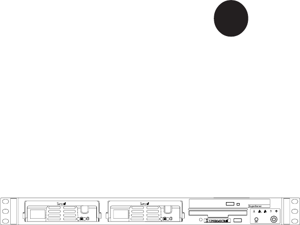
Chapter 1: Introduction 1-3 Server Chassis Features The SuperServer 5014C-T is built on the SC811T-260 1U rackmount server chassis. The following is a general outline of the main features of the SC811T-260 chassis. System Power When configured as a SuperServer 5014C-T, the SC811T-260 chassis includes a single 260W power supply. Serial ATA Subsystem For the 5014C-T, the SC811T-260 chassis was designed to support two Serial ATA hard drives. The Serial ATA drives are hot-swappable units.
SUPERSERVER 5014C-T User's Manual Figure 1-2.
Chapter 1: Introduction 1-4 Contacting Supermicro Headquarters Address: Tel: Fax: Email: Web Site: SuperMicro Computer, Inc. 980 Rock Ave. San Jose, CA 95131 U.S.A. +1 (408) 503-8000 +1 (408) 503-8008 marketing@supermicro.com (General Information) support@supermicro.com (Technical Support) www.supermicro.com Europe Address: Tel: Fax: Email: SuperMicro Computer B.V. Het Sterrenbeeld 28, 5215 ML 's-Hertogenbosch, The Netherlands +31 (0) 73-6400390 +31 (0) 73-6416525 sales@supermicro.
SUPERSERVER 5014C-T User's Manual Notes 1-8
Chapter 2: Server Installation Chapter 2 Server Installation 2-1 Overview This chapter provides a quick setup checklist to get your SuperServer 5014C-T up and running. Following the steps in the order given should enable you to have the system operational within a minimal amount of time. This quick setup assumes that your 5014C-T system has come to you with the processor and memory preinstalled. If your system is not already fully integrated with a motherboard, processor, system memory etc.
SUPERSERVER 5014C-T User's Manual Choosing a Setup Location - Leave enough clearance in front of the rack to enable you to open the front door completely (~25 inches). - Leave approximately 30 inches of clearance in the back of the rack to allow for sufficient airflow and ease in servicing. - This product is for installation only in a Restricted Access Location (dedicated equipment rooms, service closets and the like).
Chapter 2: Server Installation Rack Mounting Considerations Ambient Operating Temperature If installed in a closed or multi-unit rack assembly, the ambient operating temperature of the rack environment may be greater than the ambient temperature of the room. Therefore, consideration should be given to installing the equipment in an environment compatible with the manufacturer’s maximum rated ambient temperature (Tmra).
SUPERSERVER 5014C-T User's Manual 2-4 Installing the System into a Rack This section provides information on installing the SuperServer 5014C-T into a rack unit. If the system has already been mounted into a rack, you can skip ahead to Sections 2-5 and 2-6. There are a variety of rack units on the market, which may mean the assembly procedure will differ slightly. The following is a guideline for installing the unit into a rack with the rack rails provided with the system.
Chapter 2: Server Installation Installing the Chassis Rails Position the fixed chassis rail sections you just removed along the side of the chassis making sure the five screw holes line up. Note that these two rails are left/right specific. Screw the rail securely to the side of the chassis (see Figure 2-2). Repeat this procedure for the other rail on the other side of the chassis. You will also need to attach the rail brackets when installing into a telco rack.
SUPERSERVER 5014C-T User's Manual other assembly to the other side of the rack, making sure that both are at the exact same height and with the rail guides facing inward. Installing the Server into the Rack You should now have rails attached to both the chassis and the rack unit. The next step is to install the server into the rack. Do this by lining up the rear of the chassis rails with the front of the rack rails.
Chapter 2: Server Installation Installing the Server into a Telco Rack If you are installing the SuperServer 5014C-T into a Telco type rack, follow the directions given on the previous pages for rack installation. The only difference in the installation procedure will be the positioning of the rack brackets to the rack. They should be spaced apart just enough to accomodate the width of the telco rack. Figure 2-4.
SUPERSERVER 5014C-T User's Manual 2-5 Checking the Motherboard Setup After you install the 5014C-T in the rack, you will need to open the unit to make sure the motherboard is properly installed and all the connections have been made. 1. Accessing the inside of the system (Figure 2-5) First, release the retention screws that secure the unit to the rack. Grasp the two handles on either side and pull the unit straight out until it locks (you will hear a "click").
Chapter 2: Server Installation Figure 2-5.
SUPERSERVER 5014C-T User's Manual 2-6 Checking the Drive Bay Setup Next, you should check to make sure the peripheral drives and the Serial ATA drives and Serial ATA backplane have been properly installed and all essential connections have been made. 1. Accessing the drive bays All drives can be accessed from the front of the server. For servicing the CD-ROM and floppy drives, you will need to remove the top chassis cover.
Chapter 3: System Interface Chapter 3 System Interface 3-1 Overview There are several LEDs on the control panel as well as others on the Serial ATA drive carriers to keep you constantly informed of the overall status of the system as well as the activity and health of specific components. There are also two buttons on the chassis control panel. This chapter explains the meanings of all LED indicators and the appropriate response you may need to take.
SUPERSERVER 5014C-T User's Manual 3-3 Control Panel LEDs The control panel located on the front of the chassis has five LEDs. These LEDs provide you with critical information related to different parts of the system. This section explains what each LED indicates when illuminated and any corrective action you may need to take. Overheat/Fan Fail: When this LED flashes, it indicates a fan failure.
Chapter 3: System Interface Power: Indicates power is being supplied to the system's power supply units. This LED should normally be illuminated when the system is operating. 3-4 Serial ATA Drive Carrier LED Each Serial ATA drive carrier has a green LED. When illuminated, this green LED (on the front of the Serial ATA drive carrier) indicates drive activity. A connection to the Serial ATA backplane enables this LED to blink on and off when that particular drive is being accessed.
SUPERSERVER 5014C-T User's Manual Notes 3-4
Chapter 4: System Safety Chapter 4 System Safety 4-1 Electrical Safety Precautions ! Basic electrical safety precautions should be followed to protect yourself from harm and the SuperServer 5014C-T from damage: Be aware of the locations of the power on/off switch on the chassis as well as the room's emergency power-off switch, disconnection switch or electrical outlet. If an electrical accident occurs, you can then quickly remove power from the system.
SUPERSERVER 5014C-T User's Manual Motherboard Battery: CAUTION - There is a danger of explosion if the onboard battery is installed upside down, which will reverse its polarites (see Figure 4-1). This battery must be replaced only with the same or an equivalent type recommended by the manufacturer. Dispose of used batteries according to the manufacturer's instructions. CD-ROM Laser: CAUTION - this server may have come equipped with a CD-ROM drive.
Chapter 4: System Safety 4-3 ESD Precautions ! Electrostatic discharge (ESD) is generated by two objects with different electrical charges coming into contact with each other. An electrical discharge is created to neutralize this difference, which can damage electronic components and printed circuit boards.
SUPERSERVER 5014C-T User's Manual 4-4 Operating Precautions ! Care must be taken to assure that the chassis cover is in place when the 5014C-T is operating to assure proper cooling. Out of warranty damage to the 5014C-T system can occur if this practice is not strictly followed. Figure 4-1.
Chapter 5: Advanced Motherboard Setup Chapter 5 Advanced Motherboard Setup This chapter covers the steps required to install the P8SCi motherboard into the SC811T-260 chassis, connect the data and power cables and install add-on cards. All motherboard jumpers and connections are also described. A layout and quick reference chart are included in this chapter for your reference.
SUPERSERVER 5014C-T User's Manual Unpacking The motherboard is shipped in antistatic packaging to avoid electrical static discharge. When unpacking the board, make sure the person handling it is static protected. 5-2 Motherboard Installation This section explains the first step of physically mounting the P8SCi into the SC811T-260 chassis. Following the steps in the order given will eliminate the most common problems encountered in such an installation.
Chapter 5: Advanced Motherboard Setup 5-3 Connecting Cables Now that the motherboard is installed, the next step is to connect the cables to the board. These include the data (ribbon) cables for the peripherals and control panel and the power cables. Connecting Data Cables The ribbon cables used to transfer data from the peripheral devices have been carefully routed to prevent them from blocking the flow of cooling air that moves through the system from front to back.
SUPERSERVER 5014C-T User's Manual Figure 5-1. Control Panel Header Pins 20 19 NMI Ground X X Power LED Vcc IDE LED Vcc LAN1 LED Vcc LAN2 LED Vcc Overheat/Fan Fail LED Vcc X X Ground Reset Reset Button Ground Pwr Power Button 2 1 JF1 5-4 I/O Ports The I/O ports are color coded in conformance with the PC 99 specification. See Figure 5-2 below for the colors and locations of the various I/O ports. Figure 5-2.
Chapter 5: Advanced Motherboard Setup 5-5 ! Installing Processors Avoid placing direct pressure to the top of the processor package. Always remove the power cord first before adding, removing or changing any hardware components. Processor Support The P8SCi has a single LGA775 socket, which supports Intel Pentium 4 and Intel Celeron processors. CPU socket (with load plate) Step 1. 1. Press the socket lever to release the load plate that covers the CPU socket from its locked position.
SUPERSERVER 5014C-T User's Manual North Center Edge Step 4. 4. Use your thumb and index finger to hold the CPU at the north center and south center edges of the CPU. 5. Align Pin 1 of the CPU with Pin 1 of the socket. Once aligned, carefully lower the CPU straight down and into the socket. Do not drop the CPU on the socket. Do not move the CPU horizontally or vertically. Do not rub the CPU against the surface of the socket or against any pins of the socket, which may damage the CPU and/or the socket.
Chapter 5: Advanced Motherboard Setup Heatsink Installation 1. Do not apply any thermal grease to the heatsink or the CPU die; the required amount has already been applied. 2. Place the heatsink on top of the CPU so that the four mounting holes are aligned with those on the retention mechanism. 3. Screw in two diagonal screws (eg. the #1 and the #2 screws) until just snug (do not fully tighten the screws, which may damage the CPU). 4. Finish the installation by fully tightening all four screws.
SUPERSERVER 5014C-T User's Manual 5-6 Installing Memory CAUTION! Exercise extreme care when installing or removing DIMM modules to prevent any possible damage. ! 1. Memory support The P8SCi supports up to 4 GB of DDR2-533/400 unbuffered ECC SDRAM. The P8SCi employs a dual-channel memory configuration, meaning DIMM sockets must be populated in pairs with the same size/same type of memory modules. 2. Installing memory modules Insert each memory module vertically.
Chapter 5: Advanced Motherboard Setup 5-7 1. Adding PCI Cards Expansion slots The P8SCi has two PCI-Express x1 slots, one 64-bit 133 MHz PCI-X slot and one 32-bit PCI slot. A riser card designed specifically for use in the SC811T-260 chassis is included with your system. This riser card allows an installed PCI card to sit at a 90 degree angle so it can fit inside the chassis. This riser card accommodates 64-bit PCI-X cards and is installed in the 133 MHz PCI-X slot (see Figure 5-4). Figure 5-4.
SUPERSERVER 5014C-T User's Manual 5-8 Motherboard Details Figure 5-5.
Chapter 5: Advanced Motherboard Setup P8SCi Quick Reference Jumpers J9 JBT1 JPF JPL1/PL2 JPUSB1 JPWAKE1 JWD Description Speaker Setting CMOS Clear Power Force On GLAN1/2 USB1/2 Wake Up Keyboard Wake-up Watch Dog Reset/NMI Connector COM1/COM2 Fan1-5 Floppy IDE IPMI J1 J2 J5 J11 J14 J18 JF1 JL1 JLAN1/JLAN2 JLED JSLED JWOL JWOR LE1 SATA0-3 USB0/1 USB2/3 & USB6/7 Description COM Port 1 Connector /COM Port2 Header Fan Headers Floppy Disk Drive Connector IDE Port IPMI Connector ATX Power Connector 4-Pin Powe
SUPERSERVER 5014C-T User's Manual 5-9 Connector Definitions Power Supply Connectors The primary power supply connector on the P8SCi meets the SSI (Superset ATX) 24-pin specification. Refer to the table on the right for the pin definitions of the ATX 24-pin power connector (J1). You must also connect the 4-pin J2 power connector to your power supply. Refer to the table below right for the J2 (12V) connector.
Chapter 5: Advanced Motherboard Setup PW_ON Connector PW_ON Pin Definitions (JF1) The PW_ON connector is located on pins 1 and 2 of JF1. This header should be connected to the chassis power button, which you may also configure to put the system into suspend mode (see the Power Button Mode setting in BIOS). To turn off the power when the suspend mode is enabled, depress the power button for at least 4 seconds. See the table on the right for pin definitions.
SUPERSERVER 5014C-T User's Manual IDE LED Hard Drive Activity LED Pin Definitions (JF1) The IDE LED is located on pins 13 and 14 of JF1. This LED is used to display all IDE and SATA activity on all drives. See the table on the right for pin definitions. Pin Number Definition 13 +5V 14 HD Activity Power_LED Connector The Power LED connector is located on pins 15 and 16 of JF1. This connection is used to provide LED indication of power being supplied to the system.
Chapter 5: Advanced Motherboard Setup Chassis Intrusion Chassis Intrusion Pin Definitions (JL1) Pin Number Definition 1 Intrusion Input 2 Ground The Chassis Intrusion header is designated JL1 and located near the FAN4 header. See the table on the right for pin definitions. PS/2 Keyboard and Mouse Port Pin Definitions (J14) ATX PS/2 Keyboard and PS/2 Mouse Ports Pin Number Definition Data 1 NC 2 Ground 3 VCC 4 Clock 5 NC 6 The ATX PS/2 keyboard and the PS/2 mouse ports are designated J14.
SUPERSERVER 5014C-T User's Manual Wake-On-LAN Wake-On-LAN Pin Definitions (JWOL) The Wake-On-LAN header is designated JWOL on the motherboard. See the table on the right for pin definitions. You must enable the appropriate WOL setting in BIOS to use this function. You must also have a LAN card with a Wake-OnLAN connector and cable to use this feature. Pin Number 1 2 3 Definition +5V Standby Ground Wake-up Wake-On-Ring The Wake-On-Ring header is designated JWOR.
Chapter 5: Advanced Motherboard Setup 5-10 Jumper Settings Explanation of Jumpers To modify the operation of the motherboard, jumpers can be used to choose between optional settings. Jumpers create shorts between two pins to change the function of the connector. Pin 1 is identified with a square solder pad on the printed circuit board. See the motherboard layout pages for jumper locations.
SUPERSERVER 5014C-T User's Manual USB Wake-Up Use JPUSB1 to enable or disable USB Wake-Up, which allows you to wake up the system by depressing a key on the keyboard or by clicking the mouse when either is connected to the USB0 or USB1 port. Enable the jumper to allow the system to be woken up from an S1 or S3 state in Windows OS. See the table on the right for jumper settings. This feature works with the USB0 and USB1 ports only.
Chapter 5: Advanced Motherboard Setup Keyboard Wake-Up The JPWAKE1 jumper is used to allow the system to be woken up by depressing a key on the keyboard from an S1 or S3 state in Windows OS. See the table on the right for jumper settings. Your power supply must meet ATX specification 2.01 or higher and supply 720 mA of standby power to use this feature.
SUPERSERVER 5014C-T User's Manual 5-11 Parallel Port, Floppy and Hard Drive Connections Use the following information to connect the floppy and hard disk drive cables. • The floppy disk drive cable has seven twisted wires. • A red mark on a wire typically designates the location of pin 1. • A single floppy disk drive ribbon cable has 34 wires and two connectors to provide for two floppy disk drives.
Chapter 5: Advanced Motherboard Setup Floppy Connector The floppy connector is designated "Floppy". See the table on the right for pin definitions.
SUPERSERVER 5014C-T User's Manual Notes 5-22
Chapter 6: Advanced Chassis Setup Chapter 6 Advanced Chassis Setup This chapter covers the steps required to install components and perform maintenance on the SC811T-260 chassis. For component installation, follow the steps in the order given to eliminate the most common problems encountered. If a step is unnecessary, skip ahead to the step that follows. Tools Required The only tool you will need to install components and perform maintainance is a Philips screwdriver.
SUPERSERVER 5014C-T User's Manual 6-2 Figure 6-1. Chassis Front View Figure 6-2. Chassis Rear View Control Panel The control panel (located on the front of the chassis) must be connected to the JF1 connector on the motherboard to provide you with system control buttons and status indicators. These wires have been bundled together in a ribbon cable to simplify the connection. Connect the cable from JF1 on the motherboard to JP4 on the Control Panel PCB (printed circuit board).
Chapter 6: Advanced Chassis Setup cabling out of the airflow path. The LEDs inform you of system status. See Chapter 3 for details on the LEDs and the control panel buttons. Details on JF1 can be found in Chapter 5. 6-3 System Fans Two 10-cm blower fans provide the cooling for the SuperServer 5014C-T. The chassis includes air seals under the blower fans and at the chassis cross section, which separates the drive bay area from the motherboard area of the chassis to promote better airflow.
SUPERSERVER 5014C-T User's Manual Serial ATA Drive Installation 1. Mounting a Serial ATA drive in a drive carrier The Serial ATA drives are mounted in drive carriers to simplify their installation and removal from the chassis. These carriers also help promote proper airflow for the Serial ATA drive bays. For this reason, even empty carriers without Serial ATA drives installed must remain in the chassis.
Chapter 6: Advanced Chassis Setup 2. Installing/removing hot-swap Serial ATA drives Two Serial ATA drive bays are located in the front of the chassis, making them easily accessible for installation and removal. These drives are hotswappable, meaning they can be installed and removed without powering down the system. To remove, first push the release button located beside the drive LEDs, then swing the colored handle fully out and use it to pull the unit straight out (see Figure 6-4). Figure 6-4.
SUPERSERVER 5014C-T User's Manual Serial ATA Power Cables Serial ATA power cables should be routed so that they do not block the airflow through the chassis. See the motherboard layout diagram for the location of the cable connections. Serial ATA Backplane The Serial ATA drives plug into a backplane that provides power, drive ID and bus termination. A RAID controller can be used with the backplane to provide data security.
Chapter 6: Advanced Chassis Setup 6-5 Power Supply The SuperServer 5014C-T has a single 260 watt power supply. This power supply has the capability of operating at 100 or 240 input volts. Depress the main power button on the front of the chassis and then unplug the AC power cord to completely remove power from the system before removing the power supply. Power Supply Failure If the power supply unit fails, the system will shut down and you will need to replace the power supply unit.
SUPERSERVER 5014C-T User's Manual Notes 6-8
Chapter 7: BIOS Chapter 7 BIOS 7-1 Introduction This chapter describes the AwardBIOS Setup utility for the P8SCi. The AwardBIOS is stored in a flash chip and can be easily upgraded using a floppy disk-based program. Due to periodic changes in the BIOS, some settings may have been added or deleted that might not yet be recorded in this manual. Please refer to the Manual Download area of the Supermicro web site (www.supermicro.com) for any such changes.
SUPERSERVER 5014C-T User's Manual 7-2 Running Setup *Optimal default settings are in bold text unless otherwise noted. The BIOS setup options described in this section are selected by choosing the appropriate text from the Main BIOS Setup screen. All displayed text is described in this section, although the screen display is often all you need to understand how to set the options (see on next page). When you first power on the computer, the AwardBIOS™ is immediately activated.
Chapter 7: BIOS Main BIOS Setup Menu Date/Time Set the system date and time. Key in the correct information in the "mm", "dd" and "yy" fields. Press the "Enter" key to save the data. Legacy Diskette A/Legacy Diskette B This setting allows the user to set the type of floppy disk drive installed as diskette A and diskette B. The options are None, 360Kb 5.25 in, 1.2MB 5.25 in, 720Kb 3.5 in, 1.44/1.25MB, 3.5 in and 2.88MB 3.5 in.
SUPERSERVER 5014C-T User's Manual IDE HDD Auto-Detection This option allows the user to determine the manner in which the AwardBIOS sets the settings for IDE Channel 0 to IDE Channel 3 Master Devices. The options are "None", "Auto" and "Manual.
Chapter 7: BIOS 7-4.
SUPERSERVER 5014C-T User's Manual Quick Boot If enabled, this feature allows the system to skip certain tests while booting. This will decrease the time needed to boot the system. The settings are "Enabled" and "Disabled". Quiet Boot This feature allows the user to enable "Quiet Boot". When set to Enabled, the BIOS is in the graphic mode and displays only an OEM Logo during POST while booting. If an error occurs, The system will automatically switch to the text mode.
Chapter 7: BIOS 7-4.2 Advanced Chipset Control DRAM Data Integrity Mode If enabled, this feature allows the data stored in the DRMA memory to be integrated for faster data processing. The options are ECC and NonECC. On-Chip Frame Buffer Size This setting allows you to set On-Chip Frame Buffer Size. The options are "1 MB" and "8 MB." SATA Mode This feature allows you to select the channel for SATA mode. The options are "IDE", "RAID" and "AHCI (-Advanced Host Controller Interface).
SUPERSERVER 5014C-T User's Manual PATA IDE Mode When the item -On-chip Serial ATA is set to Combined Mode, the user can select either Primary or Secondary for Parallel ATA IDE. The options are Primary and Secondary. If On-chip Serial ATA is set to Enhanced Mode, only Serial ATA will be activated, and Primary PATA IDE will be available. Secondary PATA IDE will not be available. SATA Port This setting allows you configure the setting for the SATA port. The options are P1 and P3 is Secondary.
Chapter 7: BIOS 7-4.3 I/O Device Configuration Onboard Serial Port1/Onboard Serial Port2 This setting allows the user to set the address and the corresponding IRQ for Serial Port1 and Serial Port 2. The options are "Disabled" , "3F8/IRQ4", "2F8/IRQ3", "3E8/IRQ4", "2E8/IRQ3", and "Auto". The default setting for Serial Port1 is "3F8/IRQ4" and the default for Port 2 is "2F8/IRQ3". UART Mode Select This setting allows the user to select the UART mode for the BIOS. The options are "IrDA", "ASKIR" and "Normal.
SUPERSERVER 5014C-T User's Manual Use IR Pins This item sets the usage of the IR pins. The options are "RxD2, TxD2" and "IR-Rx2Tx2". Onboard Parallel Port This setting allows the user to set the address and the corresponding IRQ for the onboard parallel port. The options are "Disabled", "378/IRQ7", "278/ IRQ5" and "3BC/IRQ7". Parallel Port Mode This setting sets the mode for the onboard Parallel port. The options are "SPP," "EPP", "ECP" "ECP+EPP" and "Normal".
Chapter 7: BIOS Initial Display From This feature sets the device that will initiate the monitor display when the system is first turned on. The options are "PCI Slot" and "PCI Ex(press)". Reset Configuration Data Enabling this setting resets the extended system configuration data when you exit setup. Do this when you have installed a new add-on and the system reconfiguration has caused such a serious conflict that the OS cannot reboot the system. The options are "Enabled" and "Disabled.
SUPERSERVER 5014C-T User's Manual Onboard LAN Boot ROM This feature allows the user to determine if the Boot ROMs of the Onboard LAN chips should be activated. If activated, the user can boot the system from the Onboard LAN chips. The options are Disabled, LAN1, LAN2 and Both. Maximum Payload Size This setting allows the BIOS to set the maximum TLP Payload size for the PCI Express devices in the system.
Chapter 7: BIOS CPU Warning Temperature This allows you to set the CPU warning temperature. If the CPU temperature reaches this threshold, an alarm will activate and a warning message will be displayed onscreen. The options are "Disabled", "60 0 C/140 0F", "65 0 C/ 149 0F", "70 0C/158 0F", "75 0C/167 0F", "80 0C/176 0F" and "85 0C/185 0F".
SUPERSERVER 5014C-T User's Manual 7-4.6 Processor & Clock Options Thermal Management This setting determines the method used by the BIOS to control the thermal management of the system. The options are "Thermal Monitor 1 (On die throttling) " and "Thermal Monitor 2 (Ratio & VID transition)." (See Section 1-4 for details.) Limit CPUID MaxVal Select "Enabled" to set CUPID maximum value to 3. Select "Disabled" for Windows XP OS. The options are "Enabled" and "Disabled.
Chapter 7: BIOS 7-4.7 DMI Event Log DMI Event Log This setting allows you to Enable or Disable the function of DMI Event Logging. The options are Disabled and Enabled. Clear All DMI Event Logs Select Yes and press to clear all DMI event logs. The default setting is "No." View DMI Event Log Highlight this item and press to view the contents of the event log. Mark DMI Events as Read Highlight this item and press to mark the DMI events as read.
SUPERSERVER 5014C-T User's Manual 7-4.8 Console Redirection Console Redirection This setting allows you to Enable or Disable the function of Console Redirection. The options are Disabled and Enabled. BAUD Rate Select the BAUD rate for console redirection. The options are 300, 1200, 2400, 9600, 19.2K, 38.4K, 57.6K and 115.2K. Agent Connect Via This setting allows you to select the device to be used for Console Redirection.
Chapter 7: BIOS 7-5 Security Choose Security from the Award BIOS main menu with the Left/Right arrow keys. You should see the following display: Set Supervisor Password When the item "Set Supervisor Password" is highlighted on the above screen, press the key. When prompted, type the Supervisor Password in the dialogue box to set or to change the Supervisor Password. Set User Password When the item "Set User Password" is highlighted on the above screen, press the key.
SUPERSERVER 5014C-T User's Manual 7-6 Boot Choose Boot from the Award BIOS main menu with the Left/Right arrow keys. You should see the following display: The Award BIOS attempts to load the operating system from devices specified by the users in a user-specified sequence. Removable Device Boot Priority/Hard Drive Boot Priority/CD-ROM Boot Priority This item allows the user to select the Boot Priority of Hard Disk Devices. First Boot Device This item allows the user to set the first boot-up device.
Chapter 7: BIOS Third Boot Device This item allows the user to set the third boot-up device. The options are "Floppy", "LS120", "HDD", "SCSI", "CDROM", "ZIP100", "USB-FDD", "USBZIP", "USB-CDROM", "USB-HDD", "LAN" and "Disabled". Boot Other Device If enabled, this option enables the BIOS to load the OS from another device rather than the ones that have been specified as the first, second and third boot up devices. The settings are "Enabled" and "Disabled".
SUPERSERVER 5014C-T User's Manual 7-7 Exit Choose Exit from the Award BIOS main menu with the Left/Right arrow keys. You should see the following display: Save & Exit Setup When the item "Save & Exit Setup" is highlighted, press to save the changes you've made in the BIOS program (CMOS) and exit. Your system should, then, continue with the boot-up procedure.
Appendix A: BIOS POST Messages Appendix A BIOS POST Messages During the Power-On Self-Test (POST), the BIOS will check for problems. If a problem is found, the BIOS will activate an alarm or display a message. The following is a list of such BIOS messages.
SUPERSERVER 5014C-T User's Manual Notes A-2
Appendix B: Award BIOS POST Codes Appendix B Award BIOS POST Codes This section lists the POST (Power On Self Testing) Codes for the Award BIOS. POST (hex) CFh C0h C1h C3h C5h 0h1 02h 03h 04h 05h 06h 07h 08h 09h 0Ah 0Bh 0Ch 0Dh 0Eh Description Test CMOS R/W functionality. Early chipset initialization: -Disable shadow RAM -Disable L2 cache (socket 7 or below) -Program basic chipset registers Detect memory -Auto-detection of DRAM size, type and ECC.
SUPERSERVER 5014C-T User's Manual POST (hex) 0Fh 10h 11h 12h 13h 14h 15h 16h 17h 18h 19h 1Ah 1Bh 1Ch 1Dh 1Eh 1Fh 20h 21h 22h 23h 24h 25h 26h 27h 28h 29h 2Ah 2Bh 2Ch Description Reserved Auto detect flash type to load appropriate flash R/W codes into the run time area in F000 for ESCD & DMI support. Reserved Use walking 1’s algorithm to check out interface in CMOS circuitry. Also set real-time clock power status, and then check for override. Reserved Program chipset default values into chipset.
Appendix B: Award BIOS POST Codes POST (hex) 2Dh 2Eh 2Fh 30h 31h 32h 33h 34h 35h 36h 37h 38h 39h 3Ah 3Bh 3Ch 3Dh 3Eh 3Fh 40h 41h 42h 43h 44h 45h 46h 47h 48h 49h 4Ah 4Bh 4Ch 4Dh 4Eh 4Fh 50h 51h 52h 53h 54h 55h 56h 57h Description 1. Initialize multi-language 2. Put information on screen display, including Award title, CPU type, CPU speed …. Reserved Reserved Reserved Reserved Reserved Reset keyboard except Winbond 977 series Super I/O chips.
SUPERSERVER 5014C-T User's Manual POST (hex) 58h 59h 5Ah 5Bh 5Ch 5Dh 5Eh 5Fh 60h 61h 62h 63h 64h 65h 66h 67h 68h 69h 6Ah 6Bh 6Ch 6Dh 6Eh 6Fh 70h 71h 72h 73h 74h 75h 76h 77h 78h 79h 7Ah 7Bh 7Ch 7Dh 7Eh 7Fh Description Reserved Initialize the combined Trend Anti-Virus code. Reserved (Optional Feature) Show message for entering AWDFLASH.EXE from FDD (optional) Reserved 1. Initialize Init_Onboard_Super_IO switch. 2. Initialize Init_Onboard_AUDIO switch. Reserved Reserved Okay to enter Setup utility; i.e.
Appendix B: Award BIOS POST Codes POST (hex) Description 80h 81h 82h Reserved Reserved 1. Call chipset power management hook. 2. Recover the text font used by EPA logo (not for full screen logo) 3. If password is set, ask for password. Save all data in stack back to CMOS Initialize ISA PnP boot devices 1. USB final Initialization 2. NET PC: Build SYSID structure 3. Switch screen back to text mode 4. Set up ACPI table at top of memory. 5. Invoke ISA adapter ROMs 6. Assign IRQs to PCI devices 7.
SUPERSERVER 5014C-T User's Manual Notes B-6
Appendix C: Software Installation Appendix C Software Installation After all the hardware has been installed, you must first configure Intel's ICH6R SATA RAID before installing the Windows Operating System and other software drivers. The necessary drivers are all included on the Supermicro CDs that came packaged with your motherboard. (If you do not wish to configure onboard SATA RAID functions, please go directly to Section C-5 to install the Operating System & software.
SUPERSERVER 5014C-T User's Manual ATA Operating Modes You can select from the following two modes: Legacy mode and Native mode. SATA Operating Modes You can select from the following modes: Auto, Combined, Enhanced and SATA Only Mode.
Appendix C: Software Installation Using the ICH6R SATA RAID Utility Program Creating, Deleting and Reseting RAID Volumes 1. After the system exits the BIOS Setup Utility, the system will automatically reboot. The following screen appears after the Power-On Self Test. 2. When you see the above screen, press the and the keys simultaneously, the following screen of the main menu of the SATA RAID Utility will appear: Creating a RAID Volume 1.
SUPERSERVER 5014C-T User's Manual 2. Specify the RAID volume name and press the key or the key to go to the next field. (Use the key to return to the previous menu.) 3.Use the, , and keys to enter the appropriate values for the items selected and go to the next field. 4. When asked "Are you sure you want to create this volume (Y/N)", press "Y" to confirm the selection, or type "N" to change and to recreate the RAID volume.
Appendix C: Software Installation 5. You will return to the main menu with DISK/VOLUME INFORMATION updated as shown in the following screen. 6. Once the above screen appears, use the key to select "Exit" and press the key.
SUPERSERVER 5014C-T User's Manual 7. When asked "Are you sure you want to exit? (Y/N):", type "Y" to confirm the selections and exit the "Create RAID Volume" menu. Press the key to return to the main menu. Deleting a RAID Volume 1. In the main menu, use the and the arrow keys to select "Delete RAID Volume" in the main menu. Press the key and the following screen will appear: 2.Select the volume and press the key to delete the RAID volume.
Appendix C: Software Installation 3. When asked "Are you sure you want to delete this volume?", type "Y" to confirm and press the key to return to the main menu. (Use the key to return to the previous menu.) Reset Disks to Non-RAID 1. In the main menu, use the and the arrow keys to select "Reset Disks to Non-RAID".
SUPERSERVER 5014C-T User's Manual 2. When asked "Are you sure you want to reset all RAID data (Y/N):", type "Y" to confirm the selection, and press the key to return to the main menu. Exiting the ICH6R SATA RAID Configuration Utility Program 1. In the main menu, use the and the arrow keys to select "Exit" and then press the key. 2.
Appendix C: Software Installation C-3 Installing Drivers and Other Software Programs After the operating system has been installed, you may need to install some additional software drivers. The necessary drivers are all included on the Supermicro CDs that came packaged with your motherboard. (For Windows 2003, please refer to page C-14.
SUPERSERVER 5014C-T User's Manual Supero Doctor III The Supero Doctor III program is a web-based management tool that supports remote management capabilities with both remote and local management tools. The local management tool is called the Supero Doctor III Client. Supero Doctor III (which is included on the CD-ROM that came with your motherboard) allows you to monitor the environment and operations of your system.
Appendix C: Software Installation Supero Doctor III Interface (Remote Control Screen) Supero Doctor III revision 1.0 can be downloaded from our website at ftp://ftp.supermicro.com/utility/Supero_Doctor_III/. You can also download the SDIII User's Guide at: http://www.supermicro.com/PRODUCT/Manuals/ SDIII/UserGuide.pdf. For Linux, we recommend using Supero Doctor II.
SUPERSERVER 5014C-T User's Manual Notes C-12
Appendix D: System Specifications Appendix D System Specifications Processors Single Intel® Pentium® 4 LGA775 ("Prescott" type) processors with hyper-threading technology at an 800/533 MHz FSB speed or single Intel® Celeron® processors at a 533 MHz FSB speed. Note: Please refer to the support section of our web site for a complete listing of supported processors (http://www.supermicro.com/support/).
SUPERSERVER 5014C-T User's Manual Chassis Model: SC811T-260: (1U Rackmount) Dimensions: (WxHxD) 16.7 x 1.7 x 22 in. (424 x 43 x 559 mm) Weight Net (Bare Bone): 28 lbs. (12.7 kg.) Net (Gross): 34 lbs. (15.5 kg.) System Cooling Two (2) 10-cm ball bearing blower fans System Input Requirements AC Input Voltage: 100-240 VAC Rated Input Current: 115V to 230V (5A max) Rated Input Frequency: 50 to 60 Hz Power Supply Rated Output Power: 260W (Model# EFA250, Part# PWS-0055) Rated Output Voltages: +3.
Appendix D: System Specifications Regulatory Compliance Electromagnetic Emissions: FCC Class B, EN 55022 Class B, EN 61000-3-2/-3-3, CISPR 22 Class B Electromagnetic Immunity: EN 55024/CISPR 24, (EN 61000-4-2, EN 61000-4-3, EN 61000-4-4, EN 61000-4-5, EN 61000-4-6, EN 61000-4-8, EN 61000-4-11) Safety: EN 60950/IEC 60950-Compliant UL Listed (USA) CUL Listed (Canada) TUV Certified (Germany) CE Marking (Europe) D-3
SUPERSERVER 5014C-T User's Manual Notes D-4