
User`s manual


5-2
SUPERSERVER 6018R-WTR(T) USER'S MANUAL
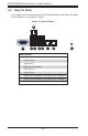
5-2 Connecting Cables
Now that the serverboard is installed, the next step is to connect the cables to the
board. These include the data cables for the peripherals and control panel and the
power cables.
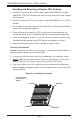
Connecting Data Cables
The cables used to transfer data from the peripheral devices have been carefully
routed to prevent them from blocking the fl ow of cooling air that moves through
the system from front to back. If you need to disconnect any of these cables, you
should take care to keep them routed as they were originally after reconnecting
them (make sure the red wires connect to the pin 1 locations). The following data
cables (with their locations noted) should be connected. (See the layout on page
5-10 for connector locations.)
• One 77-cm 10-pin to 10-pin 26-AWG two-channel USB cable (CBL-0263L)
• Two 29-cm 30-AWG SATA cables (CBL-0483L)
• One 27-cm 8-pin to 8-pin round SGPIO cable (CBL-CDAT-0660)
• One 40-cm 8-pin to 8-pin round SGPIO cable (CBL-CDAT-0661)
• One 61.5-cm 28-AWG SGPIO cable (CBL-CDAT-0662)
• Two 31-cm 30-AWG SATA cables (CBL-SAST-0639)
• Two 38-cm 30-AWG SATA cables (CBL-SAST-0640)
• Two 45-cm 30-AWG SATA cables (CBL-SAST-0641)
• Two 55-cm 30-AWG SATA cables (CBL-0488L)
Important! Make sure the cables do not come into contact with the fans.
Connecting Power Cables
The X10DRW-i(T) has a 24-pin primary power supply connector (JPW1) for
connection to the ATX power supply. In addition, there are two 8-pin 12V processor
power connectors (JPW2 and JPW3) that must be connected to your power supply.
See Section 5-9 for power connector pin defi nitions.