
User`s manual


Chapter 5: Advanced Serverboard Setup
5-15
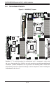
5-7 Connector Defi nitions
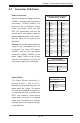
Power Connectors
A 24-pin main power supply connector
(JPWR1), and two 8-pin CPU power
connectors (JPWR2/JPWR3) are
located on the serverboard. These
power connectors meet the SSI
EPS 12V specifi cation and must be
connected to your power supply to
provide adequate power to the system.
See the tables on the right for pin
defi nitions.
Warning: To provide adequate power
supply to the serverboard, be sure
to connect the 24-pin ATX power
(JPWR1), and the two 8-pin power
connectors (JPWR2, JPWR3) to the
power supply. Failure to do so may
void the manufacturer warranty on
your power supply and serverboard.
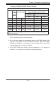
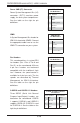
ATX Power 24-pin Connector
Pin Defi nitions (JPWR1)
Pin# Defi nition Pin # Defi nition
13 +3.3V 1 +3.3V
14 -12V 2 +3.3V
15 COM 3 COM
16 PS_ON 4 +5V
17 COM 5 COM
18 COM 6 +5V
19 COM 7 COM
20 Res (NC) 8 PWR_OK
21 +5V 9 5VSB
22 +5V 10 +12V
23 +5V 11 +12V
24 COM 12 +3.3V
12V 8-pin Power
Connector Pin Defi nitions
Pins Defi nition
1 through 4 Ground
5 through 8 +12V
(Required)
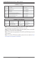
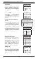
Power Button
The Power Button connection is
located on pins 1 and 2 of JF1.
Momentarily contacting both pins will
power on/off the system. This button
can also be confi gured to function as
a suspend button (with a setting in the
BIOS - See Chapter 4). To turn off the
power when the system is in suspend
mode, press the button for 4 seconds
or longer. Refer to the table on the right
for pin defi nitions.
Power Button
Pin Defi nitions (JF1)
Pin# Defi nition
1 Signal
2 Ground