
User`s manual


5-16
SUPERSERVER 6018R-WTR(T) USER'S MANUAL
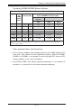
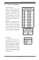
NIC1/NIC2 LED Indicators
The NIC (Network Interface Controller)
LED connection for LAN Port 1 is
located on pins 11 and 12 of JF1, and
for LAN Port 2 is on pins 9 and 10.
Attach the NIC LED cables here to
display network activity. Refer to the
table on the right for pin defi nitions.
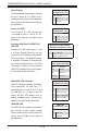
HDD/UID LED
The HDD LED connection is located on
pins 13 and 14 of JF1. Attach a cable
here to indicate HDD activity and UID
status. See the table on the right for
pin defi nitions.
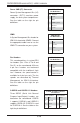
HDD LED
Pin Defi nitions (JF1)
Pin# Defi nition
13 UID LED
14 HD Active
GLAN1/2 LED
Pin Defi nitions (JF1)
Pin# Defi nition
9 NIC 2 Activity LED
10 NIC 2 Link LED
11 NIC 1 Activity LED
12 NIC 1 Link LED
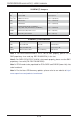
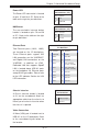
Overheat (OH)/Fan Fail/PWR Fail/
UID LED
Connect an LED cable to pins 7 and
8 of Front Control Panel to use the
Overheat/Fan Fail/Power Fail and UID
LED connections. The Red LED on pin
8 provides warnings of overheating,
fan failure or power failure. The Blue
LED on pin 7 works as the front panel
UID LED indicator. Refer to the tables
on the right for pin defi nitions.
OH/Fan Fail/ PWR Fail/Blue_
UID LED Pin Defi nitions (JF1)
Pin# Defi nition
7 Blue_UID LED
8 OH/Fan Fail/Power Fail
OH/Fan Fail/PWR Fail
LED Status (Red LED)
State Defi nition
Off Normal
On Overheat
Flashing Fan Fail
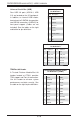
Power Fail LED
The Power Fail LED connection
is located on pins 5 and 6 of JF1.
Refer to the table on the right for pin
defi nitions.
PWR Fail LED
Pin Defi nitions (JF1)
Pin# Defi nition
5 3.3V
6 PWR Supply Fail
Reset Button
The Reset Button connection is located
on pins 3 and 4 of JF1. Attach it to a
hardware reset switch on the computer
case. Refer to the table on the right for
pin defi nitions.
Reset Button
Pin Defi nitions (JF1)
Pin# Defi nition
3 Reset
4 Ground