
User`s manual


Chapter 5: Advanced Serverboard Setup
5-17
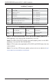
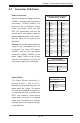
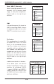
Power LED
The Power LED connection is located
on pins 15 and 16 of JF1. Refer to the
table on the right for pin defi nitions.
Power LED
Pin Defi nitions (JF1)
Pin# Defi nition
15 3.3V
16 PWR LED
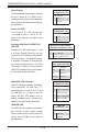
NMI Button
The non-maskable interrupt button
header is located on pins 19 and 20
of JF1. Refer to the table on the right
for pin defi nitions.
NMI Button
Pin Defi nitions (JF1)
Pin# Defi nition
19 Control
20 Ground
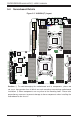
Video Connection
A Video (VGA) port is located next to
USB 0/1 on the I/O backplane. Refer
to the serverboard layout below for
the location.
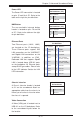
Ethernet Ports
Two Ethernet ports (LAN1, LAN2)
are located on the I/O backplane.
These Ethernet ports support 10G
LAN connections on the X10DRW-iT,
and Gigabit LAN connections on the
X10DRW-i. In addition, an IPMI_
Dedicated LAN that supports Gigabit
LAN is located above USB 0/1 ports
on the backplane. All Ethernet ports
accept RJ45 type cables. Please refer
to the LED Indicator Section for LAN
LED information.
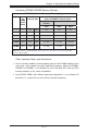
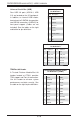
LAN Ports (LAN1/2)
Pin Defi nition
Pin# Defi nition Pin# Defi nition
1 P2V5SB 10 SGND
2 TD0+ 11 Act LED
3 TD0- 12 P3V3SB
4 TD1+ 13 Link 100 LED
(Yellow, +3V3SB)
5 TD1- 14 Link 1000 LED
(Yellow, +3V3SB)
6 TD2+ 15 Ground
7 TD2- 16 Ground
8 TD3+ 17 Ground
9 TD3- 18 Ground
Note: NC indicates no connection.
Chassis Intrusion
A Chassis Intrusion header is located
at JL1 on the serverboard. Attach an
appropriate cable from the chassis to
inform you of a chassis intrusion when
the chassis is opened.
Chassis Intrusion
Pin Defi nitions
Pin# Defi nition
1 Intrusion Input
2 Ground