
User`s manual


Chapter 5: Advanced Serverboard Setup
5-19
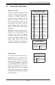
Unit Identifi er Switch/UID LED
Indicator
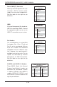
A Unit Identifi er (UID) switch is located
on the I/O backplane, and two UID
LED indicators are located on the
serverboard. The rear UID LED (LED1)
is located next to the UID switch. The
front UID LED is located on pins 7 & 8
on the front control panel (JF1). When
you press the UID switch, both rear
and front UID LED indicators will be
turned on. Press the UID switch again
to turn off the LED indicators. The UID
Indicators provide easy identifi cation
of a system unit that may be in need
of service.
Note: UID can also be triggered via
IPMI on the serverboard. For more
information on IPMI, please refer to
the IPMI User's Guide posted on our
website @
http://www.supermicro.
com.
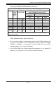
UID Switch
Pin# Defi nition
1 Ground
2 Ground
3 Button In
4 Ground
UID LED
Status
Color/State Status
Blue: On Unit Identifi ed
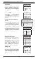
Internal Speaker
The Internal Speaker (SP1) provides
audible indications for various beep
codes. See the table on the right for pin
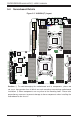
defi nitions. Refer to the layout below
for the location of the Internal Buzzer.
Internal Buzzer
Pin Defi nition
Pin# Defi nitions
Pin 1 Pos. (+) Beep In
Pin 2 Neg. (-) Alarm Speaker
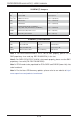
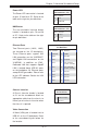
Standby Power Header
The +5V Standby Power header is
located at JSTBY1 on the serverboard.
See the table on the right for pin
defi nitions. (You must also have a card
with a Standby Power connector and a
cable to use this feature.)
Standby PWR
Pin Defi nitions
Pin# Defi nition
1 +5V Standby
2 Ground
3 No Connection