
User`s manual


5-20
SUPERSERVER 6018R-WTR(T) USER'S MANUAL
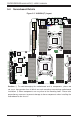
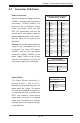
S-SGPIO and I-SGPIO 1/2 Headers
Three SGPIO (Serial Link General
Purpose Input/Output) headers are
located on the serverboard. I-SGPIO
1 supports I-SATA 0-3, and I-SGPIO 2
supports I-SATA 4/5. S-SGPIO is used
for S-SATA 0-3. See the table on the
right for pin defi nitions.
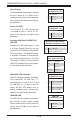
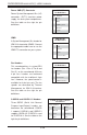
Fan Header
Pin Defi nitions
Pin# Defi nition
1 Ground
2 +12V
3 Tachometer
4 PWR Modulation
Power SMB (I
2
C) Connector
Power System Management Bus (I
2
C)
connector (JPI
2
C1) monitors power
supply, fan and system temperatures.
See the table on the right for pin
defi nitions.
PWR SMB
Pin Defi nitions
Pin# Defi nition
1 Clock
2 Data
3 PMBUS_Alert
4 Ground
5 +3.3V
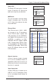
IPMB
A System Management Bus header for
IPMI 2.0 is located at JIPMB1. Connect
the appropriate cable here to use the
IPMB I
2
C connection on your system.
IPMB Header
Pin Defi nitions
Pin# Defi nition
1 Data
2 Ground
3 Clock
4 No Connection
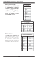
Fan Headers
This serverboard has six system/CPU
fan headers (Fan 1-Fan 4, Fan A and
Fan B ) on the serverboard. All these
4-pin fans headers are backward
compatible with the traditional 3-pin
fans. However, fan speed control is
available for 4-pin fans only. The fan
speeds are controlled by Thermal
Management via IPMI 2.0 interface.
See the table on the right for pin
defi nitions.
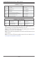
S-SGPIO & I-SGPIO 1/2 Headers
Pin Defi nitions
Pin# Defi nition Pin # Defi nition
1 NC 2 Data
3 Ground 4 Data
5 Load 6 Ground
7 CLK 8 NC
Note: NC indicates no connection.