
User`s manual

5-16
SUPERSERVER 7046T-3R User's Manual
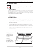
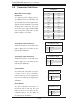
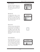
Fan Headers
There are eight fan headers on the
serverboard, all of which are 4-pin
fans. Pins 1-3 of the fan headers are
backward compatible with the tradi-
tional 3-pin fans. (Fan speed control
is supported with 4-pin fans only.)
See the table on the right for pin defi -
nitions. The onboard fan speeds are
controlled by Thermal Management
(via Hardware Monitoring) under the
Advanced Section in the BIOS. The
default is disabled. Fan 7 and FAN
8 should be used for the CPU1 and
CPU2 heatsink fans.
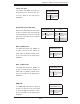
ATX PS/2 Keyboard and PS/2
Mouse Ports
The ATX PS/2 keyboard and the PS/2
mouse are located beside the USB0/1
ports. The mouse port is above the
keyboard port. See the table on the
right for pin defi nitions.
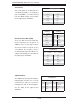
NMI Button
The non-maskable interrupt button
header is located on pins 19 and 20
of JF1. Refer to the table on the right
for pin defi nitions.
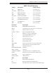
NMI Button
Pin Defi nitions (JF1)
Pin# Defi nition
19 Control
20 Ground
Fan Header
Pin Defi nitions
Pin# Defi nition
1 Ground (Black)
2 +12V (Red)
3 Tachometer
4 PWM Control
PS/2 Keyboard and
Mouse Port Pin
Defi nitions
Pin# Defi nition
1 Data
2NC
3 Ground
4 VCC
5 Clock
6NC
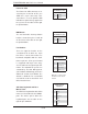
Power On LED
The Power On LED connector is lo-
cated on pins 15 and 16 of JF1 (use
JLED for a 3-pin connector). This
connection is used to provide LED
indication of power being supplied to
the system. See the table on the right
for pin defi nitions.
Power LED
Pin Defi nitions (JF1)
Pin# Defi nition
15 5V Stby
16 Control
Note: Fan 7 is for the CPU1
and Fan8 is for the CPU2
heatsink.