
Datasheet


Chapter 5: Advanced Motherboard Setup
5-3
5-3 Connecting Cables
Now that the motherboard is installed, the next step is to connect the cables to
the board. These include the data (ribbon) cables for the peripherals and control
panel and the power cables.
Connecting Data Cables
The ribbon cables used to transfer data from the peripheral devices have
been carefully routed to prevent them from blocking the flow of cooling air
that moves through the system from front to back. If you need to discon-
nect any of these cables, you should take care to keep them routed as they
were originally after reconnecting them (make sure the red wires connect
to the pin 1 locations). The following data cables (with their locations
noted) should be connected. (See the layout on page 5-10 for connector
locations.)
IDE Device cable (J5)
Serial ATA Device cables (JS1, JS2, JS3 and JS4)
Serial ATA active LED cable (JS9)
Control Panel cable (JF1)
Connecting Power Cables
The P4SCT+ has a 24-pin primary power supply connector ("ATX Power") at J20
for connection to the ATX power supply. In addition, there is a 4-pin secondary
power connector at J21 that also must be connected to your power supply. See
Chapter 5 for power connector pin definitions.
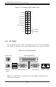
Connecting the Control Panel
JF1 contains header pins for various front control panel connectors. See
Figure 5-1 for the pin locations of the various front control panel buttons
and LED indicators.
All JF1 wires have been bundled into a single ribbon cable to simplify this
connection. Make sure the red wire plugs into pin 1 as marked on the
board. The other end connects to the Control Panel PCB board, located just
behind the system status LEDs on the chassis. See Chapter 5 for details
and pin descriptions.