
Datasheet


Chapter 5: Advanced Motherboard Setup
5-11
5-9 Connector
Definitions
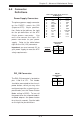
Power Supply Connectors
The primary power supply connector
on the P4SCT+ meets the SSI
(Superset ATX) 24-pin specifica-
tion. Refer to the table on the right
for the pin definitions of the ATX
24-pin power connector. You
must also connect the 4-pin J21
power connector to your power
supply. Refer to the table below
right for the J24 (12V) connector.
Important: you must connect J21 to
your power supply to meet the ATX
safety requirements.
Pins #
1 & 2
3 & 4
Definition
Ground
+12 V
+12V 4-pin PWR
Connector
(J21)
Required
Connection
ATX Power Supply 24-pin Connector
Pin Definitions
Pin Number Definition
13 +3.3V
14 -12V
15 COM
16 PS_ON#
17 COM
18 COM
19 COM
20 Res(NC)
21 +5V
22 +5V
23 +5V
24 COM
Pin Number Definition
1 +3.3V
2 +3.3V
3 COM
4 +5V
5 COM
6 +5V
7 COM
8 PWR_OK
9 5VSB
10 +12V
11 +12V
12 +3.3V
PW_ON Connector
The PW_ON connector is located on
pins 1 and 2 of JF1. This header
should be connected to the chassis
power button, which you may also
configure to put the system into sus-
pend mode (see the Power Button
Mode setting in BIOS). To turn off
the power when the suspend mode is
enabled, depress the power button
for at least 4 seconds. See the table
on the right for pin definitions.
Pin
Number
1
2
Definition
PW_ON
+3V
PW_ON
Pin Definitions
(JF1)