
Datasheet


5-12
SUPERSERVER 5013C-MT User's Manual
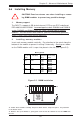
Reset Connector
The reset connector is located on
pins 3 and 4 of JF1 and attaches
to the reset switch on the com-
puter chassis. See the table on
the right for pin definitions.
Pin
Number
3
4
Definition
Reset
Ground
Reset Pin
Definitions
(JF1)
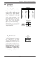
Overheat LED (OH)
Connect an LED to the OH connec-
tion on pins 7 and 8 of JF1 to pro-
vide advanced warning of chassis
overheating. Refer to the table on
the right for pin definitions.
Overheat (OH) LED
Pin Definitions
(JF1)
Pin
Number
7
8
Definition
Vcc
GND
GLAN1 LED
The GLAN1 LED connection is lo-
cated on pins 11 and 12 of JF1. At-
tach the GLAN1 LED cable to dis-
play GLAN1 activity. Refer to the
table on the right for pin definitions.
GLAN1 LED Pin
Definitions
(JF1)
Pin
Number
11
12
Definition
Vcc
GND
GLAN2 LED
The GLAN2 LED connection is lo-
cated on pins 9 and 10 of JF1. At-
tach the GLAN2 LED cable to dis-
play GLAN2 activity. Refer to the
table on the right for pin definitions.
GLAN2 LED
Pin Definitions
(JF1)
Pin
Number
9
10
Definition
Vcc
GND