
Datasheet


Chapter 5: Advanced Motherboard Setup
5-13
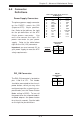
Power_LED Connector
The Power LED connector is located
on pins 15 and 16 of JF1 (or you may
use J17 for a 3-pin connector). This
connection is used to provide LED
indication of power being supplied to
the system. See the table on the
right for pin definitions.
IDE LED
The IDE LED is located on pins 13
and 14 of JF1. This LED is used to
display all IDE and SATA activity
on all drives. See the table on the
right for pin definitions.
IDE Activity LED
Pin Definitions
(JF1)
Pin
N um ber
13
14
Definition
+5V
HD Activity
Pin
Number
15
16
Definition
Vcc
Control
PWR_LED Pin Definitions
(JF1)
Pin
Number
1
2
3
Definition
+5V
Key
Ground
J17
Pin Definitions
NMI Button
The non-maskable interrupt button
header is located on pins 19 and 20
of JF1. Refer to the table on the right
for pin definitions.
Pin
Number
19
20
Definition
Ground
Control
NMI Button Pin
Definitions (JF1)
SMB Header
A System Management Bus header
is located at J15. Connect the ap-
propriate cable here to utilize SMB
on your system.
SMB Header
Pin Definitions (J15)
Pin
Number
1
2
3
4
Definition
Data
Ground
Clock
No Connection