
Datasheet


5-16
SUPERSERVER 5013C-MT User's Manual
Universal Serial Bus
(USB)
There are two Universal Serial Bus
ports located on the I/O panel and an
additional two USB headers located
on the motherboard. These head-
ers, labeled USB3/4, can be used to
provide front side chassis access
(cables not included). See the tables
on the right for pin definitions.
Pin# Definition
1 +5V
2 P0-
3 P0+
4 Ground
Pin
Number
2
4
6
8
10
Definition
+5V
PO-
PO+
Ground
Ground
Pin
Number
1
3
5
7
Definition
+5V
PO-
PO+
Ground
USB1/2 Pin Definitions
USB3/4 Pin Definitions
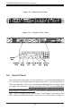
GLAN1/2 (Ethernet) Ports
Two Ethernet ports (designated
GLAN1 and GLAN2) are located
beside the VGA port on the IO
backplane. These ports accept
RJ45 type cables.
SATA LED (Marvell)
The SATA LED header located on
JS9 is used to display all SATA ac-
tivity on the JS1-JS4 SATA ports
(Marvell SATA controller). See the
table on the right for pin definitions.
SATA LED Pin Definitions
(JS9)
Pin # Definition
1 SATA1
2 SATA2
3 SATA3
4 SATA4
5 SATA LED
Comm
Pin # Definition
6 NC
7 NC
8 NC
9 NC
10 Key
SATA LED (Intel)
The SATA LED header located on
J37 is used to display all SATA ac-
tivity on the J3 and J4 SATA ports
(Intel SATA controller). See the
table on the right for pin definitions.
Intel's SATA LED
Pin Definitions
(J37)
Pin
Number
1
2
3
4
5
Definition
(I-)SATA1
(I-)SATA2
NC
NC
NC