
User`s manual


5-24
SuperWorkstation 5038A-IL User's Manual
5-10 Onboard Indicators
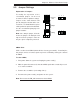
LAN1/2 LEDs
The Ethernet ports on the I/O back-
plane each have two LEDs. On each
port, one LED indicates activity while
the other LED may be green, amber
or off to indicate the speed of the
connection. See the table on the right
for the functions associated with the
connection speed LED.
LAN1/2 LED
(Connection Speed Indicator)
LED Color Defi nition
Off No Connection, 10 or 100 Mb/s
Amber 1 Gb/s
Green 10 Gb/s
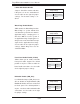
Onboard Power LED
An Onboard Power LED is located at
LE1 on the serverboard. When this
LED is on, the system is on. Be sure
to turn off the system and unplug the
power cord before removing or install-
ing components. See the table at right
for more information.
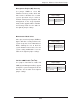
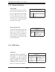
5-11 SATA Ports
SATA Port
Pin Defi nitions
Pin# Defi nition Pin # Defi nition
1 Ground 2 TXP
3 TXN 4 Ground
5 RXN 6 RXP
7 Ground
SATA Ports
Eight SATA 3.0 ports (I-SATA0/1) are
located on the serverboard. I-SATA
0-5 (RAID 0, 1, 5, 10) are supported
by the Intel C226 PCH chip while A-
SATA 0/1 (RAID 0/1) are supported by
ASM1061R SATA controller. See the
table on the right for pin defi nitions.
Onboard PWR LED Indicator
LED Status
Status Defi nition
Off System Off
On System on, or
System off and PWR
Cable Connected