
Datasheet


Chapter 5: Advanced Serverboard Setup
5-13
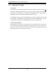
Reset Button
The Reset Button connection is lo-
cated on pins 3 and 4 of JF1. Attach
it to the hardware reset switch on the
computer case. Refer to the table on
the right for pin defi nitions.
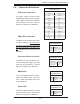
Power Button
The Power Button connection is
located on pins 1 and 2 of JF1. Mo-
mentarily contacting both pins will
power on/off the system. This button
can also be confi gured to function
as a suspend button (see the Power
Button Mode setting in BIOS). To turn
off the power when set to suspend
mode, depress the button for at least
4 seconds. Refer to the table on the
right for pin defi nitions.
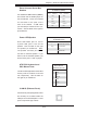
Universal Serial Bus
(USB0/1)
Two Universal Serial Bus ports are
located beside the PS/2 keyboard/
mouse ports. USB0 is the bottom
connector and USB1 is the top con-
nector. See the table on the right for
pin defi nitions.
Reset Button
Pin Defi nitions (JF1)
Pin# Defi nition
3 Reset
4 Ground
Power Button
Pin Defi nitions (JF1)
Pin# Defi nition
1 PW_ON
2 Ground
Universal Serial Bus
Pin Defi nitions (USB0/1)
USB0
Pin # Defi nition
USB1
Pin # Defi nition
1 +5V 1 +5V
2 PO- 2 PO-
3 PO+ 3 PO+
4 Ground 4 Ground
5 N/A 5 Key
Chassis Intrusion
The Chassis Intrusion header is des-
ignated at JL1. Attach the appropri-
ate cable to inform you of a chassis
intrusion.
Chassis Intrusion
Pin Defi nitions (JL1)
Pin# Defi nition
1 Intrusion Input
2 Ground