
Datasheet


5-14
S
UPERSERVER 6014H-32 User’s Manual
Fan Headers
The X6DHR-3G2 has fi ve fan head-
ers, designated Fan1 through Fan5.
Fan speed is controlled via Thermal
Management with a BIOS setting.
See the table on the right for pin
defi nitions.
Serial Ports
The COM1 serial port is located beside
the mouse port. COM2 is a header on
the serverboard (see serverboard
layout for location). See the table on
the right for pin defi nitions.
Note: Pin 10 is included on the header but not on
the port. NC indicates no connection.
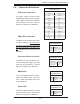
Serial Port Pin Defi nitions
(COM1/COM2)
Pin # Defi nition Pin # Defi nition
1CD 6DSR
2RD 7RTS
3TD 8CTS
4DTR 9RI
5 Ground 10 NC
Fan Header
Pin Defi nitions
(Fan1-5)
Pin# Defi nition
1 Ground (Black)
2 +12V (Red)
3 Tachometer
Overheat LED
Connect an LED to the JOH1 header
to provide warning of a chassis over-
heating condition. See the table on the
right for pin defi nitions.
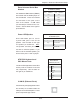
Overheat LED
Pin Defi nitions (JOH1)
Pin# Defi nition
1+5V
2 OH Active
Power Supply Fail Header
Connect a cable from your power sup-
ply to the Power Fail header to provide
you with warning of a power supply
failure. The warning signal is passed
through the PWR_LED pin to indicate
a power failure. See the table on the
right for pin defi nitions.
Power Fail Header
Pin Defi nitions (JP9)
Pin# Defi nition
1 P/S 1 Fail Signal
2 P/S 2 Fail Signal
3 P/S 3 Fail Signal
4 Reset (from MB)