
Datasheet


Chapter 7: BIOS
7-1
Chapter 7
BIOS
7-1 Introduction
This chapter describes the Phoenix BIOS™ Setup utility for the X6DHR-3G2. The
Phoenix ROM BIOS is stored in a fl ash chip and can be easily upgraded using a
fl oppy disk-based program.
Note: Due to periodic changes to the BIOS, some settings may have been added or
deleted and might not yet be recorded in this manual. Please refer to Supermicro's
web site: <http://www.supermicro.com> for any changes to BIOS that may not be
refl ected in this manual.
System BIOS
The BIOS is the Basic Input Output System used in all IBM
®
PC, XT™, AT
®
, and
PS/2
®
compatible computers. The Phoenix BIOS fl ash chip stores the system
parameters, such as type of disk drives, video displays, etc. in the CMOS. The
CMOS memory requires very little electrical power. When the computer is turned
off, a back-up battery provides power to the BIOS fl ash chip, enabling it to retain
system parameters. Whenever the computer is powered-on, the computer is con-
fi gured with the values stored in the BIOS ROM by the system BIOS, which gains
control at boot-up.
How To Change the Confi guration Data
The CMOS information that determines the system parameters may be changed by
entering the BIOS Setup utility. This Setup utility can be accessed by pressing the
<Delete> key at the appropriate time during system boot, see below.
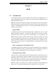
Starting the Setup Utility
Normally, the only visible POST (Power On Self Test) routine is the memory test. As
the memory is being tested, press the <Delete> key to enter the main menu of the
BIOS Setup utility. From the main menu, you can access the other setup screens,
such as the Security and Power menus. Beginning with Section 7-3, detailed de-
scriptions are given for each parameter setting in the Setup utility.
Note: fan speed is controlled by the “Fan Speed Control Mode” setting in BIOS (see
page 7-15). The recommended setting for the 6014H-32 is “3-pin (Server)”