
User`s manual


Chapter 5: Advanced Serverboard Setup
5-11
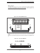
5-8 Connector Defi nitions
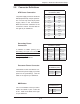
ATX Power Connection
The power supply connector meets the
SSI (Superset ATX) 20-pin specifi ca-
tion. You can only use a 20-pin power
supply cable on the serverboard.
Make sure that the orientation of the
connector is correct. See the table on
the right for pin defi nitions.
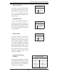
NMI Button
The non-maskable interrupt button
header is located on pins 19 and 20
of JF1. Refer to the table on the right
for pin defi nitions.
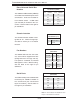
Secondary Power
Connection
In addition to JWR1 (above), the
Secondary 12v 8-pin J15 connector
(JPWR1) must also be connected to
your power supply. See the table on
the right for pin defi nitions.
NMI Button
Pin Defi nitions (JF1)
Pin# Defi nition
19 Control
20 Ground
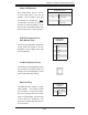
Processor Power
Pin Defi nitions (J1D1)
Pins Defi nition
1 through 4 Ground
5 through 8 +12V
Processor Power Connector
The header at J1D1 must also be con-
nected to the power supply to provide
power for the processor(s). See the
table on the right for pin defi nitions.
Secondary Power Connector
Pin Defi nitions (JPWR1)
Pin# Defi nition Pin# Defi nition
1 SMB_CLK 2 GND
3 SMB_DATA 4 PWR_Fail
5 GND 6 PWR_OK
7 PWR_ON 8 -12V
9 NC X Key
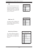
ATX Power 20-pin Connector
Pin Defi nitions (JWR1)
Pin# Defi nition Pin # Defi nition
11 +3.3V 1 +3.3V
12 -12V 2 +3.3V
13 COM 3 COM
14 PS_ON 4 +5V
15 COM 5 COM
16 COM 6 +5V
17 COM 7 COM
18 -5V 8 PW-OK
19 +5V 9 5VSB
20 +5V 10 +12V