
User`s manual


5-14
S
UPERSERVER 6014P-32/6014P-32R User’s Manual
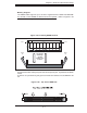
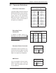
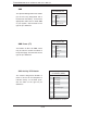
Fan Headers
The X6DHP-3G2 has fi ve fan head-
ers, each of which supports two fans
(designated Fan1 through Fan10).
Fan speed is controlled via Thermal
Management with a BIOS setting.
See the table on the right for pin
defi nitions.
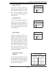
Serial Ports
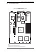
The COM1 serial port is located beside
the mouse port. COM2 is a header on
the serverboard (see serverboard
layout for location). See the table on
the right for pin defi nitions.
Note: Pin 10 is included on the header but not on
the port. NC indicates no connection.
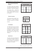
Extra Universal Serial Bus
Headers
Two additional USB headers (USB2/3)
are located near the SATA ports on the
serverboard. These are included for
front chassis access. A USB cable
(not included) is needed for the con-
nection. See the table on the right for
pin defi nitions.
Front Panel Universal Serial Bus
Pin Defi nitions (USB2/3)
USB2
Pin # Defi nition
USB3
Pin # Defi nition
1 +5V 1 +5V
2 PO- 2 PO-
3 PO+ 3 PO+
4 Ground 4 Ground
5 N/A 5 N/A
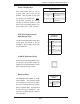
Chassis Intrusion
The Chassis Intrusion header is des-
ignated at JL1. Attach the appropri-
ate cable to inform you of a chassis
intrusion.
Chassis Intrusion
Pin Defi nitions (JL1)
Pin# Defi nition
1 Intrusion Input
2 Ground
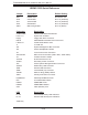
Fan Header Pin Defi nitions
(FAN1-FAN10)
Defi nition Pin# Color
Fan PWR 1 Red
Tachometer 2 Yellow
GND 3 Black
GND 4 Grey
Tachometer 5 White
Fan PWR 6 Orange
Serial Port Pin Defi nitions
(COM1/COM2)
Pin # Defi nition Pin # Defi nition
1 DCD 6 DSR
2RXD 7RTS
3TXD 8CTS
4DTR 9 RI
5 Ground 10 NC