
User`s manual


Chapter 5: Advanced Serverboard Setup
5-15
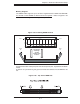
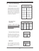
ATX PS/2 Keyboard and
PS/2 Mouse Ports
The ATX PS/2 keyboard and the PS/2
mouse ports are located on the I/O
backplane. See the table on the right
for pin defi nitions.
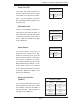
JLAN1/2 (Ethernet Ports)
Two Ethernet ports (designated JLAN1
and JLAN2) are located beside the
VGA port on the I/O backplane. These
ports accept RJ45 type cables.
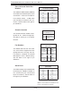
Power LED/Speaker
On the JDI header, pins 1-3 are for
a power LED, pins 4-7 are for the
speaker. See the table on the right
for speaker pin definitions. Note:
The speaker connector pins are for
use with an external speaker. If you
wish to use the onboard speaker, you
should close pins 6-7 with a jumper.
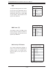
PS/2 Keyboard/ Mouse
Pin Defi nitions
(Kybd/Mouse)
Pin# Defi nition
1 Data
2NC
3 Ground
4 VCC
5 Clock
6NC
Speaker Connector
Pin Defi nitions (JD1)
Pin # Function Defi nition
4 + Speaker data (red wire)
5 Key No connection
6 Key
7 Speaker data
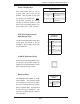
Wake-On-Ring
The Wake-On-Ring header is desig-
nated JWOR1. This function allows
your computer to receive and "wake-
up" by an incoming call to the modem
when in suspend state. See the table
on the right for pin defi nitions. You
must have a WOR card and cable to
use this feature.
Wake-On-Ring
Pin Defi nitions
(JWOR1)
Pin# Defi nition
1 Ground (Black)
2 Wake-up