
User`s manual


Chapter 6: Advanced Chassis Setup
6-9
6014P-32
The SuperServer 6014P-32 has a single 700 watt cold-swap power supply, which
is auto-switching capable. This enables it to automatically sense and operate
with a 100v - 240v input voltage. An amber light will be illuminated on the power
supply when the power is off. An illuminated green light indicates that the power
supply is operating.
Power Supply Failure
If the power supply module fails, the system will shut down and you will need to
replace the module. Replacements can be ordered directly from Supermicro (see
contact information in the Preface). As there is only one power supply module in
the 6014P-32, power must be completely removed from the server before removing
and replacing the power supply for whatever reason.
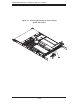
Removing/Replacing the Power Supply
1. Removing the power supply
First turn the power switch on the control panel off, then unplug the power cord from
the system. Replace with the same model - SP700-1R (p/n PWS-0065), which can
be ordered directly from Supermicro (see Contact Information in the Preface).
To remove the failed power module, fi rst locate the colored release tab (1). Push
the tab to the right (2) and then pull the module straight out with the handle provided
(3) (see Figure 6-5, redundant power supply server shown). The power supply
wiring was designed to detach automatically when the module is pulled from the
chassis.
2. Installing a new power supply
Replace the failed power supply with another SP700-1R power supply module.
Carefully insert the new power supply into the open bay and push it completely
into the chassis until you hear a clicking sound, meaning it has been fully inserted.
Finish by reconnecting the AC power cord and depressing the power button on the
chassis front control panel to restart the system.