
Datasheet


Chapter 5: Advanced Serverboard Setup
5-11
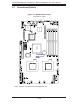
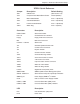
X7DCU Quick Reference
Jumper Description Default Setting
JBT1 CMOS Clear (See Section 5-9)
JCF1 Compact Flash Master/Slave Select Closed (Master)
JIDE IDE Enable/Disable Pins 1-2 (Enabled)
JPG1 VGA Enable/Disable Pins 1-2 (Enabled)
JPL1 LAN1/2 Enable/Disable Pins 1-2 (Enabled)
JWD1 Watch Dog Pins 1-2 (Reset)
Connector Description
COM1/COM2 Serial Port/Header
FAN 1-8 Chassis/CPU Fan Headers
Floppy Floppy Disk Drive Connector
IDE IDE Drive Connector
I-SATA0 ~ I-SATA5 SATA Ports
JD1 Onboard Speaker/Power LED
JF1 Control Panel Connector
JK1 Keylock Header
JL1 Chassis Intrusion Header
JOH1 Overheat Warning Header
JPW1 20-Pin ATX Power Connector
JPW2 4-Pin Power Connector
JPW3 8-pin Processor Power Connector
JWOL1 Wake-On-LAN Header
JWOR Wake-On-Ring Header
LAN1/2 Gigabit Ethernet (RJ45) Ports
SIMSO IPMI SIMSO (IPMI Remote Management) Slot
SGPIO-1/SGPIO-2 Serial General Purpose Input/Output Headers
SMBUS_PS Power Supply SMBus I
2
C Header
UIOP UIO Connector Power Supply Header
USB0/1, USB5 Universal Serial Bus (USB) Ports
USB2/3, USB4 Universal Serial Bus (USB) Headers
LED Description
LE2 Unit Identifi cation (UID) LED
LE19 Power LED