SUPER SUPERSERVER 7046GT-TRF 7046GT-TRF-TC4 USER’S MANUAL Revision 1.
The information in this User’s Manual has been carefully reviewed and is believed to be accurate. The vendor assumes no responsibility for any inaccuracies that may be contained in this document, makes no commitment to update or to keep current the information in this manual, or to notify any person or organization of the updates. Please Note: For the most up-to-date version of this manual, please see our web site at www.supermicro.com. Super Micro Computer, Inc.
Preface Preface About This Manual This manual is written for professional system integrators and PC technicians. It provides information for the installation and use of the SuperServer 7046GTTRF/7046GT-TRF-TC4. Installation and maintenance should be performed by experienced technicians only. The SuperServer 7046GT-TRF/7046GT-TRF-TC4 is based on the SC747TQR1400B 4U/Tower rackmount server chassis and the Super X8DTG-QF serverboard.
SUPERSERVER 7046GT-TRF/7046GT-TRF-TC4 User's Manual Chapter 5: Advanced Serverboard Setup Chapter 5 provides detailed information on the X8DTG-QF serverboard, including the locations and functions of connectors, headers and jumpers. Refer to this chapter when adding or removing processors or main memory and when reconfiguring the serverboard. Chapter 6: Advanced Chassis Setup Refer to Chapter 6 for detailed information on the SC747TQ-R1400B 4U/Tower rackmount server chassis.
Preface Notes v
SUPERSERVER 7046GT-TRF/7046GT-TRF-TC4 User's Manual Table of Contents Chapter 1 Introduction 1-1 Overview ......................................................................................................... 1-1 1-2 Serverboard Features ..................................................................................... 1-2 Processors ...................................................................................................... 1-2 Memory ....................................................
Table of Contents Chapter 3 System Interface 3-1 Overview ......................................................................................................... 3-1 3-2 Control Panel Buttons ..................................................................................... 3-2 3-3 Control Panel LEDs ........................................................................................ 3-2 3-4 Drive Carrier LEDs .................................................................................
SUPERSERVER 7046GT-TRF/7046GT-TRF-TC4 User's Manual Chapter 6 Advanced Chassis Setup 6-1 Static-Sensitive Devices .................................................................................. 6-2 Precautions ..................................................................................................... 6-2 6-2 Control Panel .................................................................................................. 6-2 6-3 System Cooling ...............................................
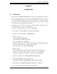
Chapter 1: Introduction Chapter 1 Introduction 1-1 Overview The SuperServer 7046GT-TRF/7046GT-TRF-TC4 is a supercomputing server that is comprised of two main subsystems: the SC747TQ-R1400B 4U/Tower server chassis and the X8DTG-QF dual Intel Xeon processor 5500 series serverboard. Please refer to our web site for information on operating systems that have been certified for use with the system (www.supermicro.com).
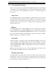
SUPERSERVER 7046GT-TRF/7046GT-TRF-TC4 User's Manual 1-2 Serverboard Features At the heart of the SuperServer 7046GT-TRF/7046GT-TRF-TC4 lies the X8DTG-QF, a dual processor serverboard based on the Intel 5520 (IOH-36D) chipset. Below are the main features of the X8DTG-QF. (See Figure 1-1 for a block diagram of the chipset). Processors The X8DTG-QF supports two Intel® 5500 Series (LGA 1366) processors supporting two full-width Intel QuickPath Interconnect (QPI) links with a total of up to 51.
Chapter 1: Introduction Onboard Controllers/Ports The color-coded I/O ports include one COM port (an additional COM header is located on the serverboard), a VGA (monitor) port, ten USB 2.0 ports (six rear USB ports, two front headers, and two Type A connections), PS/2 mouse and keyboard ports, IPMI dedicated LAN port, High Definition Audio ports and two Gb Ethernet ports.
SUPERSERVER 7046GT-TRF/7046GT-TRF-TC4 User's Manual Hard Drive/Drive Bays The SC747 Chassis features eight slots for SAS/SATA drives. These drives are hot -swappable. Once set up correctly, these drives can be removed without powering down the server. Each SC747 Chassis provides three 5.25” peripheral drive bays for floppy drives, DVD-ROM/CD-ROM Drives, or additional hard drives Front Control Panel The control panel on the server provides you with system monitoring and control.
Chapter 1: Introduction Figure 1-1. Intel 5520 Chipset: System Block Diagram Note: This is a general block diagram. Please see Chapter 5 for details. #1-6 #1-5 #1-4 #1-3 #1-2 #1-1 CSI0 QPI Ports 1,2 CSI0 PCI-Ex16 Ports 7,8,9,10 PCI-E x16 Ports 7,8,9,10 Ports 3,4,5,6 Ports 3,4,5,6 PCI-E x16 PCI-E x1 PCI-E x1 SATA2 Port5 Port6 #9 #8 #7 #6 #5 #4 #3 #2 #1 #0 ICH10R ALC888 HD USB2.
SUPERSERVER 7046GT-TRF/7046GT-TRF-TC4 User's Manual 1-5 Contacting Supermicro Headquarters Address: Super Micro Computer, Inc. 980 Rock Ave. San Jose, CA 95131 U.S.A. Tel: +1 (408) 503-8000 Fax: +1 (408) 503-8008 Email: marketing@supermicro.com (General Information) support@supermicro.com (Technical Support) Web Site: www.supermicro.com Europe Address: Super Micro Computer B.V.
Chapter 2: Server Installation Chapter 2 System Setup 2-1 Overview This chapter provides a quick setup checklist to get your SuperServer 7046GTTRF/7046GT-TRF-TC4 up and running. Following the steps in the order given should enable you to have the system operational within a minimal amount of time. If your system is not already fully integrated with a motherboard, processor, system memory etc., please turn to the chapter or section noted in each step for details on installing specific components.
SUPERSERVER 7046GT-TRF/7046GT-TRF-TC4 User's Manual 2-3 Setting Up the System You should first open the left side panel (when facing the front of the chassis) to make sure the motherboard is properly installed and all connections have been made. Warning: Only qualified service technicians should access the inside of ! the system. Except for short periods of time, do NOT operate the system without the cover in place. The chassis cover must be in place to allow proper airflow and prevent overheating.
Chapter 2: Server Installation 2. Check the SATA disk drives: Depending upon your system's configuration, your system may have up to four SATA drives already installed. If you need to install or remove an SATA drive, please refer to the appropriate section in Chapter 6. 3. Check the airflow: Cooling air is provided by the chassis fan and the power supply fan. The system component layout was carefully designed to promote sufficient airflow throughout the chassis.
SUPERSERVER 7046GT-TRF/7046GT-TRF-TC4 User's Manual ! Warnings and Precautions! ! Rack Precautions • Ensure that the leveling jacks on the bottom of the rack are fully extended to the floor with the full weight of the rack resting on them. • In single rack installation, stabilizers should be attached to the rack. • In multiple rack installations, the racks should be coupled together. • Always make sure the rack is stable before extending a component from the rack.
Chapter 2: Server Installation Rack Mounting Considerations Ambient Operating Temperature If installed in a closed or multi-unit rack assembly, the ambient operating temperature of the rack environment may be greater than the ambient temperature of the room. Therefore, consideration should be given to installing the equipment in an environment compatible with the manufacturer’s maximum rated ambient temperature (Tmra).
SUPERSERVER 7046GT-TRF/7046GT-TRF-TC4 User's Manual 2-5 Installing the Chassis onto a Rack This section provides information on installing the SC747 chassis into a rack unit with the optional 4U 17.2" width rail set (MCP-290-00059-0N). There are a variety of rack units on the market, which may mean the assembly procedure will differ slightly. You should also refer to the installation instructions that came with the rack unit you are using. NOTE: The outer rail is adjustable from 26" to 38.25".
Chapter 2: Server Installation Removing the Chassis Top Cover 1. Locate the chassis cover lock (blue lever) at the rear of the chassis cover. 2. Slide the chassis cover lock to the right and push chassis cover forward. 3. Lift the chassis top cover off the chassis. Removing the Chassis Feet 1. Place the chassis on its side with the chassis side cover facing upward. 2. Remove the screw holding the chassis foot in place. 3.
SUPERSERVER 7046GT-TRF/7046GT-TRF-TC4 User's Manual Figure 6-3: Installing the Inner Rack Rails Installing the Chassis Handles and Inner Rails Installing the Inner Rails 1. Locate the chassis handles and handle screws. 2. Align the chassis handle with the front of the chassis and secure with the three chassis handle screws. 3. Repeats steps 1 and 2 with the other handle. 4. Locate the inner rails and screws in the shipping package. 5. Align the inner rails against the chassis, as shown.
Chapter 2: Server Installation Secure to the Rear of the Rack Attach to Middle Rail Slide into the Inner Rail Figure 6-4: Assembling the Outer Rails Installing the Outer Rails to the Rack Installing the Outer Rails 1. Attach the rear bracket to the middle bracket. 2. Adjust both the brackets to the proper distance so that the rail fits snugly into the rack. 3. Secure the rear of the outer rail with two M5 screws and the rear of the rack. NOTE: The outer rail is adjustable from approximately 26" to 38.
SUPERSERVER 7046GT-TRF/7046GT-TRF-TC4 User's Manual Figure 6-5: Installing the Rack Rails Installing the Chassis into a Rack Installing the Chassis 1. Confirm that chassis includes the inner rails and the outer rails. 2. Align the inner chassis rails with the front of the outer rack rails (C). 3. Slide the inner rails into the outer rails, keeping the pressure even on both sides (you may have to depress the locking tabs when inserting).
Chapter 2: Server Installation 2-6 Tower Mounting Instructions The SC747 chassis is shipped with the chassis cover and feet pre-installed. To use the chassis as a desktop server, no other installation is required. Use the instructions in this section if you have converted the chassis for rack use and need to return the chassis to tower mounting. Chassis Cover Chassis Rack Mount Ears Chassis Feet Figure 6-6: Adding Chassis Feet and Top Cover Installing the Chassis Cover Installing the Cover 1.
SUPERSERVER 7046GT-TRF/7046GT-TRF-TC4 User's Manual Chassis Foot Receptacle Chassis Foot Chassis Screw Figure 6-7: Placing Chassis Feet Installing Feet on the Chassis Installing the Chassis Feet 1. Place the chassis foot in the foot receptacle and slide the foot toward the front of the chassis. The foot should lock into place. 2. Secure the foot to the chassis using one screw enclosed in the packaging. 3.
Chapter 3: System Interface Chapter 3 System Interface 3-1 Overview There are several LEDs on the control panel as well as others on the drive carriers to keep you constantly informed of the overall status of the system as well as the activity and health of specific components. Most SC747 models are two buttons on the chassis a control panel: a reset button and an on/off switch. This chapter explains the meanings of all LED indicators and the appropriate response you may need to take.
SUPERSERVER 7046GT-TRF/7046GT-TRF-TC4 User's Manual 3-2 Control Panel Buttons There are two push-buttons located on the front of the chassis. These are power on/off button and a reset button. • Power: The main power switch is used to apply or remove power from the power supply to the server system. Turning off system power with this button removes the main power but keeps standby power supplied to the system. Therefore, you must unplug system before servicing.
Chapter 3: System Interface • NIC2: Indicates network activity on GLAN2 when flashing. • Overheat/Fan Fail: When this LED flashes it indicates a fan failure. When continuously on (not flashing) it indicates an overheat condition, which may be caused by cables obstructing the airflow in the system or the ambient room temperature being too warm. Check the routing of the cables and make sure all fans are present and operating normally.
SUPERSERVER 7046GT-TRF/7046GT-TRF-TC4 User's Manual 3-4 Drive Carrier LEDs Your chassis uses SAS/SATA drives. SAS/SATA Drives Each SAS/SATA drive carrier has two LEDs. • Green: Each Serial ATA drive carrier has a green LED. When illuminated, this green LED (on the front of the SATA drive carrier) indicates drive activity. A connection to the SATA backplane enables this LED to blink on and off when that particular drive is being accessed. • Red: The red LED to indicate an SAS/SATA drive failure.
Chapter 4: System Safety Chapter 4 System Safety 4-1 Electrical Safety Precautions ! Basic electrical safety precautions should be followed to protect yourself from harm and the SuperServer 7046GT-TRF/7046GT-TRF-TC4 from damage: • Be aware of the locations of the power on/off switch on the chassis as well as the room's emergency power-off switch, disconnection switch or electrical outlet. If an electrical accident occurs, you can then quickly remove power from the system.
SUPERSERVER 7046GT-TRF/7046GT-TRF-TC4 User's Manual • This product may be connected to an IT power system. In all cases, make sure that the unit is also reliably connected to Earth (ground). • Serverboard Battery: CAUTION - There is a danger of explosion if the onboard battery is installed upside down, which will reverse its polarites (see Figure 4-1). This battery must be replaced only with the same or an equivalent type recommended by the manufacturer.
Chapter 4: System Safety • Remove any jewelry or metal objects from your body, which are excellent metal conductors that can create short circuits and harm you if they come into contact with printed circuit boards or areas where power is present. • After accessing the inside of the system, close the system back up and secure it to the rack unit with the retention screws after ensuring that all connections have been made.
SUPERSERVER 7046GT-TRF/7046GT-TRF-TC4 User's Manual 4-4 Operating Precautions ! Care must be taken to assure that the chassis cover is in place when the 7046GTTRF/7046GT-TRF-TC4 is operating to assure proper cooling. Out of warranty damage to the system can occur if this practice is not strictly followed. Figure 4-1. Installing the Onboard Battery LITHIUM BATTERY BATTERY HOLDER ! Please handle used batteries carefully.
Chapter 5: Advanced Serverboard Setup Chapter 5 Advanced Serverboard Setup This chapter covers the steps required to install the X8DTG-QF serverboard into the chassis, connect the data and power cables and install add-on cards. All serverboard jumpers and connections are also described. A layout and quick reference chart are included in this chapter for your reference. Remember to completely close the chassis when you have finished working with the serverboard to better cool and protect the system.
SUPERSERVER 7046GT-TRF/7046GT-TRF-TC4 User's Manual Unpacking The serverboard is shipped in antistatic packaging to avoid electrical static discharge. When unpacking the board, make sure the person handling it is static protected. 5-2 Serverboard Installation This section describes how to install the serverboard into the SC747 chassis system. Warning: To avoid damaging the serverboard and its components, do not ! apply any force greater than 8 lbs.
Chapter 5: Advanced Serverboard Setup 5-3 Connecting Cables Now that the serverboard is installed, the next step is to connect the cables to the board. These include the data (ribbon) cables for the peripherals and control panel and the power cables. Connecting Data Cables The ribbon cables used to transfer data from the peripheral devices have been carefully routed to prevent them from blocking the flow of cooling air that moves through the system from front to back.
SUPERSERVER 7046GT-TRF/7046GT-TRF-TC4 User's Manual Figure 5-4. Control Panel Header Pins 20 19 Ground No Connection x (Key) x (Key) Power On LED 3.3V HDD LED FP UID/3.3V Stby NIC1 LED (Link) NIC1 LED (Activity) NIC2 LED (Link) NIC2 LED (Activity) OH/Fan Fail/PWR Fail/UID LED Blue LED (UID Cathode)/5V Stby PWR Fail LED 3.3V Ground Reset (Button) Ground Power (Button) 2 5-4 1 I/O Ports The I/O ports are color coded in conformance with the PC 99 specification.
Chapter 5: Advanced Serverboard Setup Back Panel Connectors 1. Keyboard (Purple) 2. PS/2 Mouse (Green) 3. COM Port 1 (Turquoise) 4. VGA (Blue) 5. USB 0 6. USB1 7. IPMI_Dedicated LAN 8. USB 2 9. USB 3 10. USB 4 11. USB 5 12. LAN 2 13. LAN 1 14. Side_surround 15. Back_surround 16. CEN/LFE 17. Microphone_In 18. Front 19.
SUPERSERVER 7046GT-TRF/7046GT-TRF-TC4 User's Manual 5-5 Installing the Processor and Heatsink Warning: Avoid placing direct pressure to the top of the processor package. Always remove the power cord first before adding, removing ! or changing any hardware components. Notes: • Always connect the power cord last and always remove it before adding, removing or changing any hardware components. Make sure that you install the processor into the CPU socket before you install the CPU heatsink.
Chapter 5: Advanced Serverboard Setup CPU 1. After removing the plastic cap, use your thumb and the index finger to hold the CPU at the north and south center edges. 2. Align the CPU key (the semi-circle cutout) with the socket key (the notch below the gold color dot on the side of CPU Socket the socket). 3. Once the CPU and the socket are aligned, carefully lower the CPU straight CPU down into the socket.
SUPERSERVER 7046GT-TRF/7046GT-TRF-TC4 User's Manual Installation and Removal of the Heatsink Installing the Heatsink 1. Do not apply any thermal grease to the heatsink or the CPU die; the required amount has already been applied. 2. Place the heatsink on top of the CPU so Screw #1 that the four mounting holes are aligned with those on the retention mechanism. 3. Screw in two diagonal screws (i.e. the #1 and the #2 screws) until just snug (do not over-tighten the screws, which may damage the CPU.
Chapter 5: Advanced Serverboard Setup 5-6 Installing Memory CAUTION! Exercise extreme care when installing or removing DIMM ! modules to prevent any possible damage. Memory Support The X8DTG-QF supports up to 96 GB of registered ECC or up to 24 GB of unbuffered ECC/non-ECC DDR3-1333/1066/800 MHz SDRAM in 12 DIMM slots. See the following table for memory installation. Notes: With unbuffered ECC/non-ECC memory, 2 GB is the maximum DIMM size that can be supported per slot.
SUPERSERVER 7046GT-TRF/7046GT-TRF-TC4 User's Manual Memory Population for Optimal Performance -For a motherboard with One CPU (CPU1) installed O Branch 0 Branch 1 Branch 2 3 DIMMs P1 DIMM1A P1 DIMM2A P1 DIMM3A 6 DIMMs P1 DIMM1A P1 DIMM1B P1 DIMM2A P1 DIMM2B P1 DIMM3A P1 DIMM3B Memory Population for Optimal Performance -For a motherboard with One CPU (CPU2) installed Branch 0 Branch 1 Branch 2 3 DIMMs P2 DIMM1A P2 DIMM2A P2 DIMM3A 6 DIMMs P2 DIMM1A P2 DIMM1B P2 DIMM2A P2 DIMM2B P2
Chapter 5: Advanced Serverboard Setup DIMM Module Population Configuration For memory to work properly, follow the tables below for memory installation: DIMM Population Table DIMM Slots per Channel DIMMs Populated per Channel DIMM Type (Reg.= Registered) Speeds (in MHz) Ranks per DIMM (any combination; SR=Single Rank, DR=Dual Rank, QR=Quad Rank) 2 1 Reg. DDR3 ECC 800,1066,1333 SR or DR 2 1 Reg. DDR3 ECC 800,1066 QR 2 2 Reg. DDR3 ECC 800,1066 Mixing SR, DR 2 2 Reg.
SUPERSERVER 7046GT-TRF/7046GT-TRF-TC4 User's Manual 5-6 Adding PCI Add-On Cards The SuperServer 7046GT-TRF can support four PCI-E Gen. 2.0 x16 cards (in Slot 4, Slot 6, Slot 8 and Slot 10), one PCI-E Gen. 2.0 x4 (in x16) card (Slot 2), one PCI-E 2.0 x4 (in x8) card (Slot 11), one PCI-E Gen. 1.0 x4 (in x16) card (Slot 1) and two PCI 33 MHz cards (Slot 3, Slot 5) for a total of nine (9) PCI expansion cards.
Chapter 5: Advanced Serverboard Setup Figure 5-8: Removing the PCI Card Slot Guard 4. Remove the screw holding the bracket in place and pull the bracket from the chassis. 5. Install your PCI card or other add-on card into the PCI slot bracket and motherboard. To do this, slide the PCI card (with "L" bracket) into the PCI slot and secure the card to the motherboard. 6. Push the PCI bracket release tab down until it locks into place with an audible "click". 7.
SUPERSERVER 7046GT-TRF/7046GT-TRF-TC4 User's Manual Figure 5-9: Installing Graphics Cards 12 1 Installing Double-Width Graphics Cards The SC747 chassis is designed to support up to four double-width, high-end graphics cards. A (part number) bracket is recommended for this application and may be purchased by visiting the Supermicro Web site at http://www.supermicro.com and clicking on the Where to Buy link. Installing Double-Width Graphics Cards 1.
Chapter 5: Advanced Serverboard Setup Figure 5-10: Closing the Graphics Card Bracket 15 16 14 13 3. Place the tabs of the (part number) graphics card bracket into the slots on the wall of the chassis as illustrated in Figure 5-10. 4. Lower the bracket down onto the card 5. Pull back the slide lock and lower it over the raised tab as illustrated. 6. Push the slide lock forward, allowing the pins of the slide lock to penetrate the thru holes in the raised tab.
SUPERSERVER 7046GT-TRF/7046GT-TRF-TC4 User's Manual 5-7 Serverboard Details P2-DIMM3A PWR I2C FAN7/CPU1 JPI2C FAN5 P2-DIMM3B KB/MOUSE FAN6 JPW2 JPW1 JPW3 FAN1 JPUSB1 Figure 5-11.
Chapter 5: Advanced Serverboard Setup X8DTG-QF Quick Reference Jumper Description Default Setting JBT1 CMOS Clear (See Section 2-8) JI2C1/JI2C2 SMB to PCI/PCI-E Slots Open/Open (Disabled) JL2 Audio Mode Select Open (HD Mode) JPAC Audio Enable Pins 1-2 (Enable) JPG1 VGA Enable Pins 1-2 (Enabled) JPL1/JPL2 LAN1/2 Enable Pins 1-2 (Normal) JPRST1 Alarm Reset Enable Open (Enabled) JPT1 TPM Support Enable Pins 1-2 (Enabled) JPUSB1 Back USB Wake-up Enable Pins 1-2 (Enabled) JPUSB2 F
SUPERSERVER 7046GT-TRF/7046GT-TRF-TC4 User's Manual LED Description DP1 Onboard Standby PWR warning LED Indicator D33 BMC LED Indicator 5-8 Connector Definitions Main ATX Power Supply Connector The primary power supply connector (JPW1) is a proprietary design. Refer to the table on the right for the pin definitions of this connector. You must also connect the 8-pin (JPW2/ JPW3) graphics card power connectors to your power supply (see below).
Chapter 5: Advanced Serverboard Setup Power Button Connector Power Button Pin Definitions (JF1) The PW_ON connector is on pins 1 and 2 of JF1. Momentarily contacting both pins will power on/off the system. This button can also be configured to function as a suspend button (with a setting in the BIOS - see Chapter 4). To turn off the power when set to suspend Pin# Definition 1 Power 2 Ground mode, press the button for at least 4 seconds. Refer to the table on the right for pin definitions.
SUPERSERVER 7046GT-TRF/7046GT-TRF-TC4 User's Manual NIC2 (JLAN2) LED The LED connections for JLAN2 are on pins 9 and 10 of JF1. Attach an LED cable to display network activity. See the table on the right for pin definitions. NIC1 (JLAN1) LED The LED connections for JLAN1 are on pins 11 and 12 of JF1. Attach an LED cable to display network activity. See the table on the right for pin definitions. HDD/FP UID Button The HDD/UID button connections are located on pins 13/14 of JF1.
Chapter 5: Advanced Serverboard Setup Fan Headers Fan Header Pin Definitions The X8DTG-QF has ten chassis/system fan headers (Fan1 to Fan10). Fan 7 and Fan 8 Pin# Definition are CPU Fans. All these 4-pin fans headers 1 Ground (Black) are backward compatible with the traditional 2 +12V (Red) 3-pin fans. Fan speed control is available for 4-pin fans but not supported by 3-pin fans.
SUPERSERVER 7046GT-TRF/7046GT-TRF-TC4 User's Manual LAN1/2 (Ethernet Ports) Two Ethernet ports are located next to the USB 2~5 on the IO Backplane. In addition, LAN Ports Pin Definition Pin# Definition Pin# Definitions an IPMI Dedicated LAN is located above 1 P2V5SB 10 SGND the USB ports 0/1. These ports accept RJ45 2 TD0+ 11 Act LED type cables.
Chapter 5: Advanced Serverboard Setup (Back_Panel) High Definition Audio (HD Audio) HD Audio 3 6 2 5 1 4 This motherboard features a 7.1+2 Channel High Definition Audio (HDA) codec that provides 10 DAC channels. The HD Audio connections simultaneously supports (BP) HD Audio multiple-streaming 7.1 sound playback with 2 channels of independent stereo output for front L&R, rear L&R, center and subwoofer speakers. Use the software included in the CD-ROM with your motherboard to use this feature.
SUPERSERVER 7046GT-TRF/7046GT-TRF-TC4 User's Manual Power LED/Speaker PWR LED Connector Pin Definitions On JD1 header, pins 1~3 are used for power LED indicator and pins 4~7 are for the speaker. Connect a cable to pins 4~7 of JD1 to use an external speaker. If you wish to use the internal speaker, please close pins 6~7 with a jumper. See the tables on the right Pin Setting Definition Pin 1 Anode (+) Pin2 Cathode (-) Pin3 NA Speaker Connector Pin Definitions for pin definitions.
Chapter 5: Advanced Serverboard Setup Overheat LED/Fan Fail (JOH1) Overheat LED Pin Definitions The JOH1 header is used to connect an LED indicator to provide warnings of chas- Pin# tion sis overheating or fan failure. This LED will 1 Defini5vDC blink when a fan failure occurs. Refer to the table on right for pin definitions. OH/Fan Fail LED Pin Definitions State Message Solid Overheat Blinking Fan Fail Wake-On-LAN The Wake-On-LAN header is located at JWOL on the motherboard.
SUPERSERVER 7046GT-TRF/7046GT-TRF-TC4 User's Manual 5-9 Jumper Settings Explanation of Jumpers To modify the operation of the serverboard, jumpers can be used to choose between optional settings. 3 2 1 3 2 1 Connector Pins Jumpers create shorts between two pins to change the function of the connector. Pin 1 is identified with a square Jumper solder pad on the printed circuit board. See the serverboard layout pages for jumper locations.
Chapter 5: Advanced Serverboard Setup LAN1/2 Enable/Disable Change the setting of jumper JPL1/JPL2 to enable or disable the LAN1/LAN2 Ethernet LAN1/2 Enable/Disable Jumper Settings Jumper Setting Definition ports on the serverboard. See the table on Pins 1-2 Enabled the right for jumper settings. The default set- Pins 2-3 Disabled ting is enabled. Watch Dog Enable/Disable JWD controls the Watch Dog function. Watch Dog is a system monitor that can reboot the system when a software application hangs.
SUPERSERVER 7046GT-TRF/7046GT-TRF-TC4 User's Manual USB Wake-Up Backpanel USB WakeUp Enable (JPUSB1) Jumper Settings JPUSB1/JPUSB2 jumpers allow you to "wake up" the system by pressing a key on Pin# Definition the USB keyboard or by clicking the USB mouse of your system. JPUSB1 is used for 1-2 Enabled (default) 2-3 Disabled Backpanel USB Ports #0~5, and JPUSB2 is for Front Panel USB Ports #6~9.
Chapter 5: Advanced Serverboard Setup 5-10 Onboard Indicators GLAN LEDs Activity LED Link LED Activity LED Link LED There are two GLAN ports on the motherboard. An additional IPMI dedicated LAN port is also located above the USB 0/1 ports on the backpanel. Each Gigabit Ethernet Rear View (when facing the rear side of the chassis) LAN port has two LEDs.
SUPERSERVER 7046GT-TRF/7046GT-TRF-TC4 User's Manual 5-11 SATA Ports Serial ATA Ports Serial ATA Pin Definitions Six Serial ATA Ports (I-SATA0~I-SATA 5) are located below the onboard battery on Pin# Definition the motherboard. These ports, supported by 1 Ground Intel ICH10R (South Bridge), provide serial- 2 TX_P link signal transmission, which is faster than that of the traditional Parallel ATA. See the 3 TX_N 4 Ground table on the right for pin definitions.
Chapter 5: Advanced Serverboard Setup 5-12 Installing Software After the hardware has been installed, you should first install the operating system and then the drivers. The necessary drivers are all included on the Supermicro CDs that came packaged with your motherboard. Figure 5-12. Driver/Tool Installation Display Screen Note: Click the icons showing a hand writing on paper to view the readme files for each item.
SUPERSERVER 7046GT-TRF/7046GT-TRF-TC4 User's Manual Supero Doctor III The Supero Doctor III program is a Web base management tool that supports remote management capability. It includes Remote and Local Management tools. The local management is called SD III Client. The Supero Doctor III program included on the CD-ROM that came with your motherboard allows you to monitor the environment and operations of your system.
Chapter 5: Advanced Serverboard Setup Figure 5-14. Supero Doctor III Interface Display Screen (Remote Control) Note: SD III Software Revision 1.0 can be downloaded from our Web Site at: ftp://ftp. supermicro.com/utility/Supero_Doctor_III/. You can also download the SDIII User's Guide at: . For Linux, we will recommend using Supero Doctor II.
SUPERSERVER 7046GT-TRF/7046GT-TRF-TC4 User's Manual Notes 5-34
Chapter 6: Advanced Chassis Setup Chapter 6 Advanced Chassis Setup This chapter covers the steps required to install components and perform maintenance on the chassis. The only tool you will need to install components and perform maintenance is a Phillips screwdriver. Print this page to use as a reference while setting up your chassis. Tools Required: The only tool you will need to install components and perform maintenance is a Philips screwdriver.
SUPERSERVER 7046GT-TRF/7046GT-TRF-TC4 User's Manual 6-1 Static-Sensitive Devices Electrostatic Discharge (ESD) can damage electronic components. To prevent damage to any printed circuit boards (PCBs), it is important to handle them very carefully. The following measures are generally sufficient to protect your equipment from ESD damage: Precautions • • • Use a grounded wrist strap designed to prevent static discharge. Touch a grounded metal object before removing any board from its antistatic bag.
Chapter 6: Advanced Chassis Setup The control panel LEDs inform you of system status. See "Chapter 3: System Interface" for details on the LEDs and the control panel buttons. Details on JF1 can be found in "Chapter 5: Advanced Serverboard Installation." 6-3 System Cooling Six heavy-duty fans provide cooling for the chassis. Four fans are located in the mid-section of the chassis with two fans in the rear.
SUPERSERVER 7046GT-TRF/7046GT-TRF-TC4 User's Manual Figure 6-3: Mid-System Chassis Fans Mid Fan Release Tab Figure 6-4: Rear System Chassis Fans Rear Fan Release Tab 6-4
Chapter 6: Advanced Chassis Setup 6-4 Power Supply The SC747 chassis has a 1400W (redundant) power supply. This power supply is auto-switching capable. This enables it to automatically sense and operate at a 100v to 240v input voltage. An amber light will be illuminated on the power supply when the power is off. An illuminated green light indicates that the power supply is operating. Power Supply Failure If the power supply module fails, the system will shut down and you will need to replace the module.
SUPERSERVER 7046GT-TRF/7046GT-TRF-TC4 User's Manual Figure 6-5: Power Supply Release Button Release Button Power Supply Connections Connect each of the following cables, as required, by your motherboard manufacturer. In some instances, some cables may not need to be connected. Some cables may not be available with your model. Power Supply Cables Name 20-pin or 24-pin power cable Qty Connects to: 1 Motherboard Description 20-pin or 24-pin power cable provides electricity to the motherboard.
Chapter 6: Advanced Chassis Setup 6-5 Configuring the the Storage Module This section covers configuring the storage module in the SC747 chassis. Figure 6-6: Chassis in Rack Mount Mode Storage Module Figure 6-7: Chassis in Tower Mode Storage Module Tower or Rack Configuration The SC747 chassis is shipped in tower mode and can be immediately used as desktop server.
SUPERSERVER 7046GT-TRF/7046GT-TRF-TC4 User's Manual Rotating the Storage Module Use the procedure below to rotate the storage module for rack configuration. Figure 6-8: Removing the Storage Module Storage Module Storage Module Release Lever Rotating the Storage Module for Rack Mounting 1. Open the chassis cover. 2. Locate the storage module and disconnect any cables from the storage module to any component in the chassis. 3. Push the storage module release lever.
Chapter 6: Advanced Chassis Setup 5. Turn the storage module 90 degrees (as illustrated). 6. Reinsert the module into the chassis and reconnect the cords. Installing Drives in the Storage Module The storage module (Figure 6-9) includes three full sized drive bays and the front LED panel. The storage module can be configured in one of three ways: • Add up to three extra hard drives to the drive trays. • Add up to three peripheral drives (CD-ROM, DVD-ROM, etc.) drive trays.
SUPERSERVER 7046GT-TRF/7046GT-TRF-TC4 User's Manual Removing a Drive Carrier Use the procedure below to add hard drives to the drive carriers. Adding Hard Drives to the Drive Carriers 1. Open the chassis cover. 2. Locate the drive tray release tab for the slot you want to place the peripheral drive (see Figure 6-10). 3. Push the drive tray toward the front of the chassis.
Chapter 6: Advanced Chassis Setup 4. Place the hard drive to the hard drive tray. Make sure The hard drive can be SAS or SCSI depending on your motherboard. The hard drive may not completely fill the tray. See Figure 6-11 for details. 5. Secure the hard drive to the carrier with four screws from the bottom. 6. Slide the hard drive into the chassis until the carrier clicks into place. 7. Repeat these steps for each hard drive carrier.
SUPERSERVER 7046GT-TRF/7046GT-TRF-TC4 User's Manual Adding Peripheral Drives You can add up to three peripheral drives (DVD-ROM, CD-ROM, floppy drive, etc.) to the drive trays using the procedure below. Adding Peripheral Drives 1. Open the chassis cover. 2. Locate the drive tray release tab for the slot you want to place the peripheral drive. 3. Push the drive tray toward the front of the chassis. 4. Remove the hard drive tray rails from the hard drive tray.
Chapter 6: Advanced Chassis Setup 6-6 Installing Hard Drives in the Chassis Chassis hard drives are mounted in drive carriers to simplify their installation and removal from the chassis. These carriers also help promote proper airflow for the drive bays. Installing Hard Drives 1. Unlock and open the chassis cover. 2. Press the release button to extend the drive tray handle (see Figure 6-14). 3. Using the handle, pull the drive tray out by the handle.
SUPERSERVER 7046GT-TRF/7046GT-TRF-TC4 User's Manual 5. Place a hard drive in the drive tray (see Figure 6-15). 6. Secure the hard drive to the tray using four screws. Figure 6-15: Removing a Dummy Drive Tray Drive Tray SAS/SATA Hard Drive 7. Insert the hard drive into the chassis. To do this: a. Press the hard drive release button to extend the drive tray handle. b. Insert the hard drive into the chassis and close the handle to lock the hard drive into place (see Figure 6-16).
Chapter 7: BIOS Chapter 7 BIOS 7-1 Introduction This chapter describes the AMI BIOS Setup Utility for the X8DTG-QF. The AMI ROM BIOS is stored in a Flash EEPROM and can be easily updated. This chapter describes the basic navigation of the AMI BIOS Setup Utility setup screens. Starting BIOS Setup Utility To enter the AMI BIOS Setup Utility screens, press the key while the system is booting up. Note: In most cases, the key is used to invoke the AMI BIOS setup screen.
SUPERSERVER 7046GT-TRF/7046GT-TRF-TC4 User's Manual Starting the Setup Utility Normally, the only visible Power-On Self-Test (POST) routine is the memory test. As the memory is being tested, press the key to enter the main menu of the AMI BIOS Setup Utility. From the main menu, you can access the other setup screens. An AMI BIOS identification string is displayed at the left bottom corner of the screen below the copyright message.
Chapter 7: BIOS Supermicro X8DTG-QF • BIOS Build Version: This item displays the BIOS revision used in your system. • BIOS Build Date: This item displays the date when this BIOS was completed. Processor The AMI BIOS will automatically display the status of the processor used in your system: • CPU Type: This item displays the type of CPU used in the motherboard. • Speed: This item displays the speed of the CPU detected by the BIOS.
SUPERSERVER 7046GT-TRF/7046GT-TRF-TC4 User's Manual 7-3 Advanced Setup Configurations Use the arrow keys to select the Boot Setup submenu, and hit to access the following items: XBoot Features Quick Boot If Enabled, this option will skip certain tests during POST to reduce the time needed for system boot. The options are Enabled and Disabled. Quiet Boot This option allows the bootup screen options to be modified between POST messages or the OEM logo. Select Disabled to display the POST messages.
Chapter 7: BIOS Wait For 'F1' If Error This forces the system to wait until the 'F1' key is pressed if an error occurs. The options are Disabled and Enabled. Hit 'Del' Message Display This feature displays "Press DEL to run Setup" during POST. The options are Enabled and Disabled. Watch Dog Function If enabled, the Watch Dog Timer will allow the system to reboot when it is inactive for more than 5 minutes. The options are Enabled and Disabled.
SUPERSERVER 7046GT-TRF/7046GT-TRF-TC4 User's Manual Ratio CMOS Setting This option allows the user to set the ratio between the CPU Core Clock and the FSB Frequency. The default setting depends on what type of CPU is installed. For example, the default setting is [21]. Press <+> or <-> on your keyboard to change this value. Note: if an invalid ratio is entered, the AMI BIOS will restore the setting to the previous state.
Chapter 7: BIOS Execute-Disable Bit Capability (Available when supported by the OS and the CPU) Set to Enabled to enable the Execute Disable Bit which will allow the processor to designate areas in the system memory where an application code can execute and where it cannot, thus preventing a worm or a virus from flooding illegal codes to overwhelm the processor or damage the system during an attack. The default is Enabled. (Refer to Intel and Microsoft Web Sites for more information.
SUPERSERVER 7046GT-TRF/7046GT-TRF-TC4 User's Manual C3 Auto Demotion When enabled, the CPU will conditionally demote C6 or C7 requests to C3 based on un-core auto-demote information. The options are Disabled and Enabled. ACPI T State Select Enabled to report processor throttling in ACPI. The options are Disabled and Enabled. DCA Technology When set to Enabled, this feature accelerates the performance of TOE devices.
Chapter 7: BIOS Memory Frequency This feature forces a DDR3 frequency slower than what the system has detected to run at the frequency as specified. The available options are Auto, Force DDR800, Force DDR-1066, Force DDR-1333 and Force SPD. Memory Mode The options are Independent, Channel Mirror, Lockstep and Sparing. Independent - All DIMMs are available to the operating system. Channel Mirror - The motherboard maintains two identical copies of all data in memory for redundancy.
SUPERSERVER 7046GT-TRF/7046GT-TRF-TC4 User's Manual Inlet Temperature This is the temperature detected at the chassis inlet. Each step is in 0.5oC increments. The default is [070]. Temperature Rise This is the temperature rise used for the DIMM thermal zone. Each step is in 0.5oC increments. Air Flow This is the air flow speed to the DIMM modules. Each step is one mm/sec. The default is [1500]. Altitude This feature defines how many meters above or below sea level the system is located.
Chapter 7: BIOS NUMA Support Select Enabled to efficiently execute applications under Non-Uniform Memory Architecture (NUMA)-aware Operating Systems. Select Disabled for better memory access under non-NUMA aware Operating Systems. The options are Enabled and Disabled. Intel I/OAT The Intel I/OAT (I/O Acceleration Technology) significantly reduces CPU overhead by leveraging CPU architectural improvements, thus freeing resources for other tasks. The options are Disabled and Enabled.
SUPERSERVER 7046GT-TRF/7046GT-TRF-TC4 User's Manual XIDE/SATA/Floppy Configuration When this submenu is selected, the AMI BIOS automatically detects the presence of the IDE devices and displays the following items: SATA#1 Configuration Select Compatible to set SATA#1 to legacy compatibility mode. Select Enhanced to set SATA#1 to native SATA mode. The options are Disabled, Compatible and Enhanced. Configure SATA#1 as This feature allows the user to select the drive type for SATA#1.
Chapter 7: BIOS LBA/Large Mode LBA (Logical Block Addressing) is a method of addressing data on a disk drive. In the LBA mode, the maximum drive capacity is 137 GB. For drive capacities over 137 GB, your system must be equipped with a 48-bit LBA mode addressing. If not, contact your manufacturer or install an ATA/133 IDE controller card that supports 48-bit LBA mode. The options are Disabled and Auto.
SUPERSERVER 7046GT-TRF/7046GT-TRF-TC4 User's Manual DMA Mode Select Auto to allow the BIOS to automatically detect IDE DMA mode when the IDE disk drive support cannot be determined. Select SWDMA0 to allow the BIOS to use Single Word DMA mode 0. It has a data transfer rate of 2.1 MB/s. Select SWDMA1 to allow the BIOS to use Single Word DMA mode 1. It has a data transfer rate of 4.2 MB/s. Select SWDMA2 to allow the BIOS to use Single Word DMA mode 2. It has a data transfer rate of 8.3 MB/s.
Chapter 7: BIOS 32Bit Data Transfer Select Enable to enable 32-bit IDE data transferring support. The options are Enabled and Disabled. XPCI/PnP Configuration Clear NVRAM This feature clears the NVRAM during system boot. The options are No and Yes. Plug & Play OS Selecting Yes allows the OS to configure Plug & Play devices. (This is not required for system boot if your system has an OS that supports Plug & Play.) Select No to allow the AMI BIOS to configure all devices in the system.
SUPERSERVER 7046GT-TRF/7046GT-TRF-TC4 User's Manual Load Onboard LAN 1 Option ROM/Load Onboard LAN 2 Option ROM Select Enabled to enable onboard LAN1/LAN2 Option ROMs support which will allow you to boot your systems using a network interface. The options are Enabled and Disabled. Graphic Adapter Boot Priority This option selects the graphics adapter the system uses as the primary boot device. The options are Other, Onboard VGA and Slot 6.
Chapter 7: BIOS Flow Control This feature allows the user to set the flow control for Console Redirection. The options are None, Hardware, and Software. Redirection After BIOS POST Select Disabled to turn off Console Redirection after Power-On Self-Test (POST). Select Always to keep Console Redirection active all the time after POST. (Note: This setting may not be supported by some operating systems.) Select Boot Loader to keep Console Redirection active during POST and Boot Loader.
SUPERSERVER 7046GT-TRF/7046GT-TRF-TC4 User's Manual The options are: • The Early Alarm: Select this setting if you want the CPU overheat alarm (including the LED and the buzzer) to be triggered as soon as the CPU temperature reaches the CPU overheat threshold as predefined by the CPU manufacturer.
Chapter 7: BIOS User intervention: No action is required. However, consider checking the CPU fans and the chassis ventilation for blockage. High – The processor is running hot. This is a ‘caution’ level since the CPU’s ‘Temperature Tolerance’ has been reached (or has been exceeded) and may activate an overheat alarm. User intervention: If the system buzzer and Overheat LED has activated, take action immediately by checking the system fans, chassis ventilation and room temperature to correct any problems.
SUPERSERVER 7046GT-TRF/7046GT-TRF-TC4 User's Manual XACPI Configuration Use this feature to configure Advanced Configuration and Power Interface (ACPI) power management settings for your system.
Chapter 7: BIOS ACPI Version Features The options are ACPI v1.0, ACPI v2.0 and ACPI v3.0. Please refer to ACPI's website for further explanation: http://www.acpi.info/. XTrusted Computing (This option is available for OEM only.) TCG/TPM Support Select Yes to enable support for trusted platforms (TPM 1.1/1.2) and allow the BIOS to automatically download the drivers needed to provide support for the platforms specified. The options are Yes and No.
SUPERSERVER 7046GT-TRF/7046GT-TRF-TC4 User's Manual XIPMI Configuration Intelligent Platform Management Interface (IPMI) is a set of common interfaces that are used for hardware health monitoring and system management. For more information on the IPMI specifications, please visit Intel's web site at www.intel.com. IPMI Firmware Revision This item displays the IPMI firmware revision used in your system.
Chapter 7: BIOS Clear BMC System Event Log Clear BMC System Log Select OK and press the key to clear the BMC system log. Select Cancel to keep the BMC System log. The options are OK and Cancel. Caution: Any cleared information is unrecoverable. Make absolutely sure that you no longer need any data stored in the log before clearing the BMC Event Log. XSet LAN Configuration Set this feature to configure the IPMI LAN adapter with a network address as shown in the following graphics.
SUPERSERVER 7046GT-TRF/7046GT-TRF-TC4 User's Manual Subnet Mask This item displays the current subnet mask setting for your IPMI connection. Current Subnet Mask in BMC This item displays the current subnet mask setting for your IPMI connection. XGateway Address Configuration Enter the gateway address for this machine. This should be in decimal and in dotted quad form (i.e., 192.168.10.253). The value of each three-digit number separated by dots should not exceed 255 as shown in the screen below.
Chapter 7: BIOS XEvent Log Configuration View Event Log Use this option to view the System Event Log. Mark all events as read This option marks all events as read. The options are OK and Cancel. Clear event log This option clears the Event Log memory of all messages. The options are OK and Cancel. PCIe Error Log Use this option to enable logging of PCIe Errors. The options are Yes and No. Clear event log This option clears the Event Log memory of all messages. The options are OK and Cancel.
SUPERSERVER 7046GT-TRF/7046GT-TRF-TC4 User's Manual Supervisor Password This item indicates if a Supervisor password has been entered for the system. "Not Installed" means a Supervisor password has not been used. User Password This item indicates if a user password has been entered for the system. "Not Installed" means that a user password has not been used. Change Supervisor Password Select this feature and press to access the submenu, and then enter a new Supervisor Password.
Chapter 7: BIOS 7-5 Boot Configuration Use this feature to configure boot priority settings. XBoot Device Priority Use this feature to specify the sequence of boot priority for onboard devices. The settings are 1st boot device~5th boot device and Disabled. 1st Boot Device - 1st Floppy Drive/2nd Boot Device - [USB: XXXXXXXXX] XHard Disk Drives Use this feature to specify the boot sequence from all bootable HDD devices.
SUPERSERVER 7046GT-TRF/7046GT-TRF-TC4 User's Manual 7-6 Exit Options Select the Exit tab from the AMI BIOS Setup Utility screen to enter the Exit BIOS Setup screen. Save Changes and Exit When you have completed the system configuration changes, select this option to leave the BIOS Setup Utility and reboot the computer, so the new system configuration parameters can take effect. Select Save Changes and Exit from the Exit menu and press .
Chapter 7: BIOS Load Fail-Safe Defaults To set this feature, select Load Fail-Safe Defaults from the Exit menu and press . The Fail-Safe settings are designed for maximum system stability, but not for maximum performance.
SUPERSERVER 7046GT-TRF/7046GT-TRF-TC4 User's Manual Notes 7-30
Appendix A: BIOS Error Beep Codes Appendix A BIOS Error Beep Codes During the POST (Power-On Self-Test) routines, which are performed each time the system is powered on, errors may occur. Non-fatal errors are those which, in most cases, allow the system to continue the boot-up process. The error messages normally appear on the screen. Fatal errors are those which will not allow the system to continue the boot-up procedure.
SUPERSERVER 7046GT-TRF/7046GT-TRF-TC4 User's Manual Notes A-2
Appendix B: Installing Windows Appendix B Installing Windows After all hardware components have been installed, you must first configure Intel South Bridge RAID Settings before you install the Windows OS and other software drivers. To configure RAID settings, please refer to RAID Configuration User Guides posted on our web site at www.supermicro.com/support/manuals. Note: the following instructions apply to installing Windows XP or Windows 2003 only.
SUPERSERVER 7046GT-TRF/7046GT-TRF-TC4 User's Manual B-2 Installing Windows for a Non-RAID System 1. Insert Microsoft's Windows XP/Windows 2003 setup CD in the CD drive and the system will start booting up from the CD. 2. Continue with the OS installation. The Windows OS Setup screen will display. 3. From the Windows setup screen, press the key. The XP/2003 Setup will automatically load all device files and then continue with the installation. 4.
Appendix C: System Specifications Appendix C System Specifications Processors Two Intel 5500 Series (LGA 1366) processors Note: Please refer to our web site for a complete listing of supported processors.
SUPERSERVER 7046GT-TRF/7046GT-TRF-TC4 User's Manual Expansion Slots • • • • • Four PCI-E Gen. 2.0 x16 slots (Slot 4, Slot 6, Slot 8, Slot 10) One PCI-E Gen. 1.0 x4 (in x16) slot (Slot 1) One PCI-E Gen. 2.0 x4 (in x16) slot (Slot 2) One PCI-E Gen. 2.0 x4 (in x8) slot (Slot 11) Two PCI 33 MHz slots (Slot 3, Slot 5) Serverboard X8DTG-QF (proprietary ATX form factor) Dimensions: 13.00" (L) x 15.20" (W) (330.20 mm x 386.08 mm) Chassis SC747TQ-R1400B (4U/Tower rackmount) Dimensions: (WxHxD) 11.8 x 7 x 29.
Appendix C: System Specifications Regulatory Compliance Electromagnetic Emissions: FCC Class A, EN 55022 Class A, EN 61000-3-2/3-3, CISPR 22 Class A Electromagnetic Immunity: EN 55024/CISPR 24, (EN 61000-4-2, EN 61000-4-3, EN 61000-4-4, EN 61000-4-5, EN 61000-4-6, EN 61000-4-8, EN 61000-4-11) Safety: CSA/EN/IEC/UL 60950-1 Compliant, UL or CSA Listed (USA and Canada), CE Marking (Europe) California Best Management Practices Regulations for Perchlorate Materials: This Perchlorate warning applies only to prod
SUPERSERVER 7046GT-TRF/7046GT-TRF-TC4 User's Manual Notes (continued from front) The products sold by Supermicro are not intended for and will not be used in life support systems, medical equipment, nuclear facilities or systems, aircraft, aircraft devices, aircraft/emergency communication devices or other critical systems whose failure to perform be reasonably expected to result in significant injury or loss of life or catastrophic property damage.