
User`s manual


2-2
SUPERSERVER 7046GT-TRF/7046GT-TRF-TC4 User's Manual
2-3 Setting Up the System
You should fi rst open the left side panel (when facing the front of the chassis) to
make sure the motherboard is properly installed and all connections have been
made.
Warning: Only qualifi ed service technicians should access the inside of
the system. Except for short periods of time, do NOT operate the system
without the cover in place. The chassis cover must be in place to allow
proper airfl ow and prevent overheating.
!
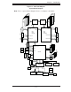
Checking the Motherboard Setup
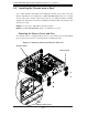
Accessing the inside of the system: Begin by disconnecting the chassis from 1.
any power source. (A) Lift up and back on the main cover handle, which
secures the cover to the chassis. (B) Lift the main cover off of the chassis.
See Chapter 5 for details on Chassis covers and how to remove them.
Check the CPU (processor): You may have a processor already installed into 2.
the system board. The processor should have its own heatsink attached. See
Chapter 5 for instructions on processor installation.
Check the system memory:3. Your system may have come with system
memory already installed. Make sure all DIMMs are fully seated in their slots.
For details on adding system memory, refer to Chapter 5.
Installing add-on cards:4. If desired, you can install up to nine add-on cards to
the system. See Chapter 5 for details on installing PCI- add-on cards.
Note: The SuperServer 7046GT-TRF-TC4 contains four Nvidia C1060 Tesla
GPU add-on card modules that occupy many of these add-on card expansion
slots.
Check all cable connections and airfl ow: Make sure all power and data cables 5.
are properly connected and not blocking the airfl ow. See Chapter 5 for details
on cable connections.
Checking the Drive Bay Setup
Next, you should check to make sure the peripheral drives and the SATA drives have
been properly installed and all essential connections have been made.
Accessing the peripheral drive bays: To install a component to either of the 1.
two 5.25" drive bays, you will need to remove the side chassis cover. See the
installation and removal sections for the peripheral drives in Chapter 6.