
User`s manual


5-18
SUPERSERVER 7046GT-TRF/7046GT-TRF-TC4 User's Manual
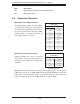
LED Description
DP1 Onboard Standby PWR warning LED Indicator
D33 BMC LED Indicator
5-8 Connector Defi nitions
Required Connection
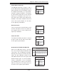
Graphics Card Power Connectors
JPW2 and JPW3 must also be connected
to the power supply to provide power for
the GPUs. See the table on the right for pin
defi nitions.
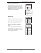
Main ATX Power Supply Connector
The primary power supply connector (JPW1)
is a proprietary design. Refer to the table on
the right for the pin defi nitions of this connec-
tor. You must also connect the 8-pin (JPW2/
JPW3) graphics card power connectors to
your power supply (see below).
20-pin Main Power Connector
Pin Defi nitions
Pin# Defi nition Pin # Defi nition
11 PS On 1 Ground
12 5VSB 2 Ground
13 Ground 3 Ground
14 Ground 4 Ground
15 Ground 5 Ground
16 NC2 6 NC1
17 12V 7 12V
18 12V 8 12V
19 12V 9 12V
20 12V 10 12V
Graphics Card Power Connector
Pin Defi nitions
Pin# Defi nition Pin # Defi nition
1 12V 5 Ground
2 12V 6 Ground
3 12V 7 Ground
4 Ground 8 Ground
Notes: For the these proprietary connectors to work properly, please customize your
PWR cables based on the SMC PWR Connector Pin-Out Defi nitions listed in the
tables above. For the PCI-Exp. Graphic cards to work properly, connect the PCI-E
graphic card power connectors (JPW2/JPW3) to the power supply.