
User`s manual


Chapter 5: Advanced Serverboard Setup
5-19
Power Button Connector
The PW_ON connector is on pins 1 and 2
of JF1. Momentarily contacting both pins will
power on/off the system. This button can also
be confi gured to function as a suspend but-
ton (with a setting in the BIOS - see Chapter
4). To turn off the power when set to suspend
mode, press the button for at least 4 sec-
onds. Refer to the table on the right for pin
defi nitions. This header should be connected
to the chassis power button. See the table
on the right for pin defi nitions.
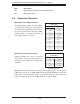
Power Button
Pin Defi nitions
(JF1)
Pin# Defi nition
1 Power
2 Ground
Overheat/Fan Fail/PWR Fail/UID LED
Connect an LED cable to pins 7 and 8 of
JF1 for the Overheat/Fan Fail/Power Fail
connections. The red LED (pin 8) provides
warning of an overheat, fan failure or power
failure. The blue LED (pin 7) works as the
UID LED indicator for the front panel UID
button located on pins 13~14 of JF1. When
Jumper J_UID_OW is set to off (default),
the red LED takes precedence over the blue
LED. (See Page 2-31 for details.) Refer to
the table on the right for pin defi nitions.
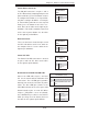
OH/Fan Fail/ PWR Fail/Blue_UID LED
Pin Defi nitions (JF1)
Pin# Defi nition
7 Blue_LED-Cathode(UID)/5.5V.SB
8 OH/Fan Fail/PWR Fail/UID LED
(Red)
OH/Fan Fail/PWR Fail
LED Status (Red LED)
State Defi nition
Off Normal
On Overheat
Flashing Fan Fail
Power Fail LED
The Power Fail LED connection is located
on pins 5 and 6 of JF1. Refer to the table
on the right for pin defi nitions.
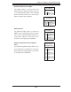
PWR Fail LED
Pin Defi nitions
(JF1)
Pin# Defi nition
5 3.3V
6 PWR Fail
LED
Reset Connector
The reset connector is located on pins 3 and
4 of JF1 and attaches to the reset switch on
the computer chassis. See the table on the
right for pin defi nitions.
Reset Button
Pin Defi nitions
(JF1)
Pin# Defi nition
3 Reset
4 Ground