
User`s manual


5-20
SUPERSERVER 7046GT-TRF/7046GT-TRF-TC4 User's Manual
NIC2 LED
Pin Defi nitions
(JF1)
Pin# Defi nition
9 Vcc
10 Ground
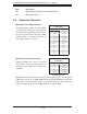
NIC2 (JLAN2) LED
The LED connections for JLAN2 are on pins
9 and 10 of JF1. Attach an LED cable to
display network activity. See the table on the
right for pin defi nitions.
NIC1 LED
Pin Defi nitions
(JF1)
Pin# Defi nition
11 Vcc
12 Ground
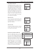
NIC1 (JLAN1) LED
The LED connections for JLAN1 are on pins
11 and 12 of JF1. Attach an LED cable to
display network activity. See the table on the
right for pin defi nitions.
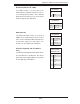
HDD/FP UID Button
The HDD/UID button connections are located
on pins 13/14 of JF1. Attach a hard-drive LED
cable to display HDD or SATA activity. This
connection can also be used for the front
panel UID (Unit Identifi er) button. (The UID
LED on pin 7 of JF1 works in conjunction with
the UID button.) When the user presses and
releases the UID button, the UID LED will be
turned on or off to indicate the location of the
unit in a stack or rackmounted servers.
HDD/UID LED
Pin Defi nitions
(JF1)
Pin# Defi nition
13 UID Signal/3.3V
14 HDD Active
Power On LED
The Power On LED connector is located
on pins 15 and 16 of JF1. This connection
is used to provide LED indication of power
being supplied to the system. See the table
on the right for pin defi nitions.
Power LED
Pin Defi nitions
(JF1)
Pin# Defi nition
15 +3.3V Stby
16 Control