
User`s manual


Chapter 5: Advanced Serverboard Setup
5-21
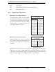
Fan Headers
The X8DTG-QF has ten chassis/system fan
headers (Fan1 to Fan10). Fan 7 and Fan 8
are CPU Fans. All these 4-pin fans headers
are backward compatible with the traditional
3-pin fans. Fan speed control is available for
4-pin fans but not supported by 3-pin fans.
The fan speeds are controlled by Thermal
Management via Hardware Monitoring in the
Advanced Setting in the BIOS. (The Default
setting is disabled.) See the table on the right
for pin defi nitions.
Fan Header
Pin Defi nitions
Pin# Defi nition
1 Ground (Black)
2 +12V (Red)
3 Tachometer
4 PWM Control
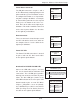
Chassis Intrusion
The Chassis Intrusion header is designated
JL1. Attach an appropriate cable from the
chassis to inform you of a chassis intrusion
when the chassis is opened
Chassis Intrusion
Pin Defi nitions
Pin# Defi nition
1 Intrusion Input
2 Ground
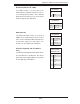
Universal Serial Bus (USB)
Six Universal Serial Bus ports (USB 0/1,
2/3/4/5) are located on the I/O back panel.
Additional four USB connections (USB 6,
7, 8/9) are used to provide front chassis
access. Connect USB cables to these USB
ports/headers to use USB connections.
(USB cables are not included). See the
tables on the right for pin defi nitions.
Back Panel USB 0/1, 2/3/4/5
Pin Defi nitions
Pin# Defi nition Pin# Defi nition
1 +5V 5 +5V
2 USB_PN1 6 USB_PN0
3 USB_PP1 7 USB_PP0
4 Ground 8 Ground
Front Panel USB 6,7, 8/9
Pin Defi nitions
USB 6, 7, 8
Pin# Defi nition
USB 9
Pin# Defi nition
1 +5V 6 +5V
2 USB_PN2 7 USB_PN3
3 USB_PP2 8 USB_PP3
4 Ground 9 Ground
5 NC 10 Key
NC = No Connection