
User`s manual


5-24
SUPERSERVER 7046GT-TRF/7046GT-TRF-TC4 User's Manual
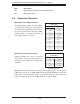
Internal Buzzer
The Internal Buzzer, located at SP1, can be
used to provide audible alarms for various
beep codes. See the table on the right for pin
defi nitions. Refer to the layout below for the
locations of the Internal Speaker/Buzzer.
Internal Buzzer
Pin Defi nitions
Pin# Defi nitions
Pin 1 Pos. (+) Beep In
Pin 2 Neg. (-) Alarm Speaker
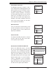
Power LED/Speaker
On JD1 header, pins 1~3 are used for
power LED indicator and pins 4~7 are for
the speaker. Connect a cable to pins 4~7 of
JD1 to use an external speaker. If you wish
to use the internal speaker, please close pins
6~7 with a jumper. See the tables on the right
for pin defi nitions.
Speaker Connector
Pin Defi nitions
Pin Setting Defi nition
Pins 4-7 External Speaker
Pins 6-7 Internal Speaker
PWR LED Connector
Pin Defi nitions
Pin Setting Defi nition
Pin 1 Anode (+)
Pin2 Cathode (-)
Pin3 NA
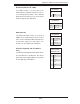
SMB (I
2
C) Connector
System Management Bus (I
2
C) Connector
(JSMB1) monitors power supply, fan and
system temperatures. See the table on the
right for pin defi nitions.
PWR SMB
Pin Defi nitions
Pin# Defi nition
1 Clock
2 Data
3 PWR Fail
4 Ground
Power SMB (I
2
C) Connector
Power System Management Bus (I
2
C) Con-
nector (JPI
2
C) monitors power supply, fan
and system temperatures. See the table on
the right for pin defi nitions.
PWR SMB
Pin Defi nitions
Pin# Defi nition
1 Clock
2 Data
3 PWR Fail
4 Ground
5 +3.3V