SUPER X6DAL-G X6DAL-TG USER’S MANUAL Revision 1.
The information in this User’s Manual has been carefully reviewed and is believed to be accurate. The vendor assumes no responsibility for any inaccuracies that may be contained in this document, makes no commitment to update or to keep current the information in this manual, or to notify any person or organization of the updates. Please Note: For the most up-to-date version of this manual, please see our web site at www.supermicro.com.
Preface Preface About This Manual This manual is written for system integrators, PC technicians and knowledgeable PC users. It provides information for the installation and use of the X6DAL-G/X6DAL-TG motherboard. The X6DALG/X6DAL-TG supports single or dual Intel ® Xeon Nocona TM processors at a 800 MHz front side bus.
X6DAL-G/X6DAL-TG User's Manual Table of Contents Preface About This Manual ...................................................................................................... iii Manual Organization ................................................................................................... iii Chapter 1: Introduction 1-1 Overview ......................................................................................................... 1-1 Checklist ..............................................
Table of Contents Power Fail LED ......................................................................................... 2-9 Reset Button ........................................................................................... 2-10 Power Button ......................................................................................... 2-10 Chassis Intrusion ................................................................................... 2-10 Universal Serial Bus (USB0/1) ..............................
X6DAL-G/X6DAL-TG User's Manual 3-2 Technical Support Procedures .................................................................... 3-2 3-3 Frequently Asked Questions ........................................................................ 3-3 3-4 Returning Merchandise for Service ............................................................ 3-5 Chapter 4: BIOS 4-1 Introduction .......................................................................................................
Chapter 1: Introduction 1-1 Introduction Chapter 1 Introduction Overview Checklist Congratulations on purchasing your computer motherboard from an acknowledged leader in the industry. Supermicro boards are designed with the utmost attention to detail to provide you with the highest standards in quality and performance. Check that the following items have all been included with your motherboard. If anything listed here is damaged or missing, contact your retailer. All are included in the retail box.
X6DAL-G/X6DAL-TG User's Manual Contacting Supermicro Headquarters Introduction Address: Tel: Fax: Email: Web Site: SuperMicro Computer, Inc. 980 Rock Ave. San Jose, CA 95131 U.S.A. +1 (408) 503-8000 +1 (408) 503-8008 marketing@supermicro.com (General Information) support@supermicro.com (Technical Support) www.supermicro.com Europe Address: Tel: Fax: Email: SuperMicro Computer B.V. Het Sterrenbeeld 28, 5215 ML 's-Hertogenbosch, The Netherlands +31 (0) 73-6400390 +31 (0) 73-6416525 sales@supermicro.
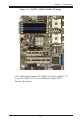
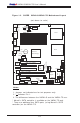
Chapter 1: Introduction SUPER X6DAL-G/X6DAL-TG Image Introduction Figure 1-1. (*The difference between the X6DAL-G and the X6DAL-TG is that the X6DAL-TG has an additional 4-port SATA Marvell Controller.
X6DAL-G/X6DAL-TG User's Manual Figure 1-2.
Chapter 1: Introduction Quick Reference ( X6DAL-G/X6DAL-TG) Description Default Setting CN1 J13 J15 J26 JBT1 JPL1 JPS1 JWD Alarm Reset Open (Disabled) SMB Data to PCI Enable Closed (Enabled) SMB Clock to PCI Enable Closed (Enabled) Audio Enable Closed (Enabled) Clear CMOS See Chapter 2 LAN1 Enable Pins 1-2 (Enabled) Marvell's SATA Enable (*X6DAL-TG)Pins 1-2 (Enabled) Watch Dog Enable Pins 2-3 (NMI) Connector Description ATX PWR Primary 24-pin ATX PWR Connector PWR2/PWR 3 12V 8-pin CPU PWR/12V 4-pin PWR
X6DAL-G/X6DAL-TG User's Manual Motherboard Features CPU Introduction • Single or dual Intel® 604-pin Nocona TM processors (*w/EM64T support) at 800 MHz front side (system) bus speed. Memory • Six 184-pin DIMM sockets supporting 12 GB/24GB Registered ECC DDR 333/266 (PC2700/PC2100) SDRAM Notes: 1. Memory size is set via BIOS. 2. Interleaved memory; requires memory modules to be installed in pairs. See Section 2-3 for details.
Chapter 1: Introduction • Microsoft OnNow • Slow blinking LED for suspend state indicator • Main switch override mechanism Onboard I/O • 1 Intel 82541PI Gigabit Ethernet controller • 2 EIDE Ultra DMA/100 bus master interfaces • 1 floppy port interface (up to 2.88 MB) • 1 EPP/ECP Parallel Port • PS/2 mouse and PS/2 keyboard ports • Up to four USB 2.
X6DAL-G/X6DAL-TG User's Manual Introduction Figure 1-9. Block Diagram of the E7525 Tumwater Chipset Note: This is a general block diagram. Please see the previous Motherboard Features pages for details on the features of each motherboard.
Chapter 1: Introduction Chipset Overview Built upon the functionality and the capability of the E7525 Tumwater chipset, the X6DAL-G/X6DAL-TG motherboard provides the performance and feature set required for dual processor-based servers, with configuration options optimized for communications, presentation, storage, computation or database applications.
X6DAL-G/X6DAL-TG User's Manual 1-3 Special Features BIOS Recovery Introduction The BIOS Recovery function allows you to recover your BIOS image file if the BIOS flashing procedure fails (see Section 3-3). Recovery from AC Power Loss BIOS provides a setting for you to determine how the system will respond when AC power is lost and then restored to the system.
Chapter 1: Introduction The thermal control sensor monitors the CPU temperature in real time and will increase the speed of the thermal control fan whenever the CPU temperature exceeds a user-defined threshold. The overheat circuitry runs independently from the CPU. It can continue to monitor for overheat conditions even when the CPU is in sleep mode.
X6DAL-G/X6DAL-TG User's Manual 1-5 ACPI Features Introduction ACPI stands for Advanced Configuration and Power Interface. The ACPI specification defines a flexible and abstract hardware interface that provides a standard way to integrate power management features throughout a PC system, including its hardware, operating system and application software. This enables the system to automatically turn on and off peripherals such as CD-ROMs, network cards, hard disk drives and printers.
Chapter 1: Introduction Wake-up events can be triggered by a device such as the external modem ringing when the system is in the SoftOff state. Note that external modem ring-on can only be used with an ATX 2.01 (or above) compliant power supply. 1-6 Power Supply As with all computer products, a stable power source is necessary for proper and reliable operation. It is even more important for processors that have high CPU clock rates. The SUPER X6DAL-G/X6DAL-TG accommodates ATX power supplies.
X6DAL-G/X6DAL-TG User's Manual 1-7 Super I/O Introduction The disk drive adapter functions of the Super I/O chip include a floppy disk drive controller that is compatible with industry standard 82077/765, a data separator, write pre-compensation circuitry, decode logic, data rate selection, a clock generator, drive interface control logic and interrupt and DMA logic.
Chapter 2: Installation Chapter 2 Installation 2-1 Static-Sensitive Devices Electric-Static-Discharge (ESD) can damage electronic components. To prevent damage to your system board, it is important to handle it very carefully. The following measures are generally sufficient to protect your equipment from ESD. Precautions • Use a grounded wrist strap designed to prevent static discharge. • Touch a grounded metal object before removing the board from the antistatic bag.
X6DAL-G/X6DAL-TG User's Manual 2-2 PGA Processor and Heatsink Installation ! When handling the processor package, avoid placing direct pressure on the label area of the fan. Also, do not place the motherboard on a conductive surface, which can damage the BIOS battery and prevent the system from booting up. IMPORTANT: Always connect the power cord last and always remove it before adding, removing or changing any hardware components.
Chapter 2: Installation 2. Insert the CPU in the socket, making sure that pin 1 of the CPU aligns with pin 1 of the socket (both corners are marked with a triangle). When using only one CPU, install it into CPU socket #1 (Socket #2 is automatically disabled if only one CPU is used). 3. Press the lever down until you hear the *click* so you can be sure that the CPU is securely installed in the CPU socket. Pin1 Socket lever in the locking Position Heatsink Installation 1.
X6DAL-G/X6DAL-TG User's Manual 1. Unscrew and remove the heatsink screws from the motherboard in the sequence as show in the second picture on the right. 2. Hold the heatsink as show in the picture on the right and gently wriggle the heatsink to loosen it from the CPU. (Do not use excessive force when wriggling the heatsink!!) 3. Once the CPU is loosened from the heatsink, remove the heatsink from the CPU socket. 4. Clean the surface of the CPU and the heatsink to get rid of the old thermal grease.
Chapter 2: Installation Mounting the Motherboard in the Chassis All motherboards have standard mounting holes to fit different types of chassis. Make sure the location of all the mounting holes for both the motherboard and the chassis match. Although a chassis may have both plastic and metal mounting fasteners, metal ones are highly recommended because they ground the motherboard to the chassis. Make sure the metal standoffs click in or are screwed in tightly.
X6DAL-G/X6DAL-TG User's Manual Figure 2-2. Installing and Removing DIMMs To Install: Insert module vertically and press down until it snaps into place. Pay attention to the alignment notch at the bottom. To Remove: Use your thumbs to gently push near the edge of both ends of the module. This should release it from the slot. 2-4 I/OPorts/Control Panel Connectors The I/O ports are color coded in conformance with the PC 99 specification.
Chapter 2: Installation Front Control Panel JF1 contains header pins for various buttons and indicators that are normally located on a control panel at the front of the chassis. These connectors are designed specifically for use with Supermicro server chassis. See Figure 2-4 for the descriptions of the various control panel buttons and LED indicators. Refer to the following section for descriptions and pin definitions. Figure 2-4.
X6DAL-G/X6DAL-TG User's Manual 2-5 Connecting Cables ATX Power Supply 24-pin Connector Pin Definitions (PW1) Pin Number Definition Pin Number Definition 1 +3.3V 13 +3.3V 2 +3.3V 14 -12V 3 COM 15 COM 4 +5V 16 PS_ON# 5 COM 17 COM 6 +5V 18 COM 7 COM 19 COM 8 PWR_OK 20 Res(NC) 9 5VSB 21 +5V 10 +12V 22 +5V 11 +12V 23 +5V 12 +3.3V 24 COM ATX Power Connector There are a 24-pin main power supply connector(PW1) and a 4pin 12V PWR connector (PW3) on the board. (Both connections are required.
Chapter 2: Installation NMI Button NMI Button Pin Definitions (JF1) Pin Number Definition 19 Control 20 Ground The non-maskable interrupt button header is located on pins 19 and 20 of JF1. Refer to the table on the right for pin definitions. Power LED PWR_LED Pin Definitions (JF1) Pin Number Definition 15 Vcc 16 Control The Power LED connection is located on pins 15 and 16 of JF1. Refer to the table on the right for pin definitions.
X6DAL-G/X6DAL-TG User's Manual HDD LED The HDD LED connection is located on pins 13 and 14 of JF1. Attach the hard drive LED cable here to display disk activity (for any hard drives on the system, including SCSI, Serial ATA and IDE). See the table on the right for pin definitions. HDD LED Pin Definitions (JF1) Pin Number Definition 13 Vcc 14 HD Active NIC1 LED Indicators The NIC (Network Interface Controller) LED connections for the GLAN port1 is located on pins 11 and 12 of JF1.
Chapter 2: Installation Overheat/Fan Fail LED Pin Definitions (JF1) Overheat/Fan Fail LED Connect an LED to the OH/Fan Fail connection on pins 7 and 8 of JF1 to provide advanced warning of chassis overheating. Refer to the table on the right for pin definitions. Pin Number Definition 7 Vcc 8 GND Overheat/Fan Fail LED State Message Overheat Fan Fail Solid Blink Power Fail LED Power Fail LED Pin Definitions (JF1) The Power Fail LED connection is located on pins 5 and 6 of JF1.
X6DAL-G/X6DAL-TG User's Manual Reset Button The Reset Button connection is located on pins 3 and 4 of JF1. Attach it to the hardware reset switch on the computer case. Refer to the table on the right for pin definitions. Reset Pin Definitions (JF1) Pin Number Definition 3 Reset 4 Ground Power Button Power Button Connector Pin Definitions (JF1) The Power Button connection is located on pins 1 and 2 of JF1. Momentarily contacting both pins will power on/off the system.
Chapter 2: Installation Chassis Intrusion Chassis Intrusion Pin Definitions Pin Definition Number Intrusion Input 1 2 Ground A Chassis Intrusion header is located at JL1. Attach the appropriate cable to inform you of a chassis intrusion.
X6DAL-G/X6DAL-TG User's Manual ATX PS/2 Keyboard and PS/2 Mouse Ports PS/2 Keyboard and Mouse Port Pin Definitions (J2) The ATX PS/2 keyboard and the PS/2 mouse are located at J2. See the table on the right for pin definitions. (The mouse port is above the keyboard port. See the table on the right for pin definitions.) Pin Number Definition 1 Data 2 NC 3 Ground 4 VCC 5 Clock 6 NC Fan Headers There are six fan headers (Fan 1 to Fan 6) on the X6DAL-G/TG). See the table on the right for pin definitions.
Chapter 2: Installation Serial Ports Serial Port Pin Definitions (COM1, COM2) The COM1 (J4) and COM2 (J5) serial ports are located under the parallel port (see Figure 2-3). See the table on the right for pin definitions.
X6DAL-G/X6DAL-TG User's Manual Wake-On-LAN Wake-On-LAN Pin Definitions (JWOL) The Wake-On-LAN header (JWOL) is designated WOL on the motherboard. See the table on the right for pin definitions. You must enable the LAN Wake-Up setting in BIOS to use this function. (You must also have a LAN card with a Wake-On-LAN connector and cable to use this feature.
Chapter 2: Installation Power Fault Power Fault Pin Definitions Connect a cable from your power supply to the Power Fault header (J7) to provide warning of power supply failure. This warning signal is passed through the PWR_LED pin to indicate of a power failure on the chassis. See the table on the right for pin definitions. Pin Number 1 2 3 4 Note: This feature is only available when using redundant Supermicro power supplies.
X6DAL-G/X6DAL-TG User's Manual SMB Power (I2 C) SMB PWR Pin Definitions (J27) Connector Pin # 1 2 3 4 5 I 2 C Connector , located at J27, monitors the status of PWR Supply, Fan and system temperature.
Chapter 2: Installation AC 97/AUX In/CD In AC'97 provides high quality onboard audio. The X6DAL-G/X6DAL-TG features 6-channel sound for front L&R, rear L&R, center and subwoofer speakers. This feature is activated with the Advanced software (on the CD-ROM included with your motherboard). Sound is then output through the Line In, Line Out and MIC jacks (see at right). Activate AC 97 with the "AC 97 Audio" setting in the Advanced Chipset Features section of BIOS.
X6DAL-G/X6DAL-TG User's Manual 2-6 Jumper Settings Explanation of Jumpers Connector Pins To modify the operation of the motherboard, jumpers can be used to choose between optional settings. Jumpers create shorts between two pins to change the function of the connector. Pin 1 is identified with a square solder pad on the printed circuit board. See the motherboard layout pages for jumper locations.
Chapter 2: Installation Alarm Reset Alarm Reset Jumper Settings The system will notify you in the event of a power supply failure. This feature assumes that Supermicro redundant power supply units are installed in the chassis. If you only have a single power supply installed, you should disable this (the default setting) with (CN1) to prevent false alarms. See the table on the right for jumper settings.
X6DAL-G/X6DAL-TG User's Manual CMOS Clear JBT1 is used to clear CMOS. Instead of pins, this "jumper" consists of contact pads to prevent the accidental clearing of CMOS. To clear CMOS, use a metal object such as a small screwdriver to touch both pads at the same time to short the connection. Always remove the AC power cord from the system before clearing CMOS. Note: For an ATX power supply, you must completely shut down the system, remove the AC power cord and then short JBT1 to clear CMOS.
Chapter 2: Installation Audio Enable/Disable Audio Enable/Disable Jumper Settings (J26) - &20 -3) 3: $7; 3:5 )RUFH 3: 2Q '6 SLQ '6 $O05VHW 3: 3: - )DXOW - 60% 3: ',00 % Definition Enabled Disabled )$1 - Jumper Position Pins 1-2 Pins 2-3 &1 86% .% 0RXVH J26 enables or disables the Audio Connector on the motherboard. See the table on the right for jumper settings. The default setting is enabled.
X6DAL-G/X6DAL-TG User's Manual Onboard Indicators G-bit LAN Right LED Indicator LED Color Off Green Orange GLAN LEDs The Gigabit Ethernet LAN port (located beside the COM Port2) has two LEDs. The yellow LED indicates activity while the other LED may be green, orange or off to indicate the speed of the connection. See the table at right for the functions associated with the second LED. - &20 )$1 -3) $7; 3:5 3 : )RUFH 3: 2Q '6 SLQ '6 $O05VHW 3: 3: - )DXOW - 60% 3: ',00 % &1 86% .
Chapter 2: Installation Onboard LED Indicators (DS1-DS8) On board LED Pin Definitions DS# Definition DS1 CPU PW R good or CPU +12V PW R Cable must be connected. CPU2 VRM Overheat DS2 CPU1 VRM Overheat DS3 PW R LED DS5 CPU Overheat DS6 POST LED DS7-8 In addition to the LAN LED and SATA Header, there are other LED indicators (DS1-DS3, DS5-DS8 ) on the X6DAL-G/TG. See the table on the right for speaker pin definitions. (*Note: Please refer to Appendix A for DS7 and DS8 LED POST Codes.
X6DAL-G/X6DAL-TG User's Manual 2-8 Parallel Port, Floppy/Hard Disk Drive and SCSI Connections Note the following when connecting the floppy and hard disk drive cables: • The floppy disk drive cable has seven twisted wires. • A red mark on a wire typically designates the location of pin 1. • A single floppy disk drive ribbon cable has 34 wires and two connectors to provide for two floppy disk drives.
Chapter 2: Installation Floppy Connector Floppy Connector Pin Definitions (J24) Pin Number 1 3 5 7 9 11 13 15 17 19 21 23 25 27 29 31 33 - &20 -3) $7; 3:5 3 : )RUFH 3: 2Q '6 SLQ 3: '6 $O05VHW 3: - )DXOW - 60% 3: ',00 % Function FDHDIN Reserved FDEDIN IndexMotor Enable Drive Select BDrive Select AMotor Enable DIRSTEPWrite DataWrite GateTrack 00Write ProtectRead DataSide 1 SelectDiskette )$1 - Function Pin Number GND 2 GND 4 Key 6 GND 8 GND 10 GND 12 GND 14 GND 16 GND 18 GND 20 GN
X6DAL-G/X6DAL-TG User's Manual IDE Connectors - &20 Pin Number 1 3 5 7 9 11 13 15 17 19 21 23 25 27 29 31 33 35 37 39 Function Pin Number Function Reset IDE 2 GND Host Data 7 4 Host Data 8 Host Data 6 6 Host Data 9 Host Data 5 8 Host Data 10 Host Data 4 10 Host Data 11 Host Data 3 12 Host Data 12 Host Data 2 14 Host Data 13 Host Data 1 16 Host Data 14 Host Data 0 18 Host Data 15 GND 20 Key DRQ3 22 GND I/O Write24 GND I/O Read26 GND IOCHRDY 28 BALE DACK330 GND IRQ14 32 IOCS16Addr 1 34 GND Addr 0 36 Ad
Chapter 3: Troubleshooting Chapter 3 Troubleshooting 3-1 Troubleshooting Procedures Use the following procedures to troubleshoot your system. If you have followed all of the procedures below and still need assistance, refer to the ‘Technical Support Procedures’ and/or ‘Returning Merchandise for Service’ section(s) in this chapter. Note: Always disconnect the power cord before adding, changing or installing any hardware components. Before Power On 1.
X6DAL-G/X6DAL-TG User's Manual NOTE If you are a system integrator, VAR or OEM, a POST diagnostics card is recommended. For I/O port 80h codes, refer to App. B. Memory Errors 1. Make sure that the DIMM modules are properly and fully installed. 2. Check if different speeds of DIMMs have been installed and verify that the BIOS setup is configured for the fastest speed of RAM used. It is recommended to use the same RAM speed for all DIMMs in the system. 3.
Chapter 3: Troubleshooting 1. Please go through the ‘Troubleshooting Procedures’ and 'Frequently Asked Question' (FAQ) sections in this chapter or see the FAQs on our web site ( http://www.supermicro.com/support/faqs/) before contacting Technical Support. 2. BIOS upgrades can be downloaded from our web site at (http://www.supermicro.com/support/bios/). Note: Not all BIOS can be flashed; it depends on the modifications to the boot block code. 3.
X6DAL-G/X6DAL-TG User's Manual Question: What's on the CD that came with my motherboard? Answer: The supplied compact disc has quite a few drivers and programs that will greatly enhance your system. We recommend that you review the CD and install the applications you need. Applications on the CD include chipset drivers for Windows and security and audio drivers. Note: The CD is a bootable disc and can be used to create driver diskettes.
Chapter 4: AMI BIOS Chapter 4 AMIBIOS 4-1 Introduction This chapter describes the AMIBIOS for the X6DAL-TG/X6DAL-G. The AMI ROM BIOS is stored in a Flash EEPROM and can be easily upgraded using a floppy disk-based program. This chapter describes the basic navigation of the AMI BIOS Setup Utility setup screens. Starting the BIOS Setup Utility To enter the AMI BIOS Setup Utility screens, hit the key while the system is booting-up.
X6DAL-G/X6DAL-TG User’s Manual 4-2 Main Setup When you first enter the AMI BIOS Setup Utility, you will enter the Main setup screen. You can always return to the Main setup screen by selecting the Main tab on the top of the screen. The Main BIOS Setup screen is shown below.
Chapter 4: AMI BIOS System Memory This option allows the AMI BIOS to display the status of memory installed in the system. Size This option allows the AMI BIOS to display the size of memory installed in the system. System Time/System Date Use this option to change the system time and date. Highlight System Time or System Date using the keys. Enter new values through the keyboard. Press the key or the keys to move between fields. The date must be entered in DAY/MM/DD/YY format.
X6DAL-G/X6DAL-TG User’s Manual X CPU Configuration Sub Menu Configure Advanced CPU Settings This option allows the user to configure Advanced CPU settings for the processor(s) installed in the system. Ratio CMOS Setting This option allows the user to set the ratio between the CPU Core Clock and the FSB Frequency. (*Note: if an invalid ratio is entered, AMIBIOS will restore the setting to the previous state.) VID CMOS Setting This option sets the VID setting for the processor(s).
Chapter 4: AMI BIOS X IDE Configuration Sub Menu The screen for the Primary IDE Master is shown below: When you select this Sub Menu, the AMI BIOS automatically displays the status of the following items: Onboard PCI IDE Operate Mode This feature allows the user to set the Onboard PCI IDE Operation Mode. The options are: Native Mode and Legacy Mode. (*Please refer to Addendum D for information on Legacy Mode and Native Mode.) IDE Configuration This feature allows the user to set the IDE mode.
X6DAL-G/X6DAL-TG User’s Manual S-ATA Ports Definition This feature allows the user to configure Serial ATA Ports. The options are: P0-Master/P1-Slave, P0-Slave/P1-Master . P-ATA Only S-ATA Running Enhanced Mode Select Yes if you want the function of Serial ATA Enanced Mode to be enabled at all times. Options are Yes and No. P-ATA Channel Selection This feature allows the user to select which channel to set the Parallel ATA Mode. The options are: Primary, Secondary or Both.
Chapter 4: AMI BIOS LBA/Large Mode LBA (Logical Block Addressing) is a method of addressing data on a disk drive. In the LBA mode, the maximum drive capacity is 137 GB. For drive capacities over 137 GB, your system must be equipped with 48-bit LBA mode addressing. If not, contact your manufacturer or install an ATA/133 IDE controller card that supports 48-bit LBA mode. The options are Disabled or Auto.
X6DAL-G/X6DAL-TG User’s Manual allow the BIOS to use Single Word DMA mode 2. It has a data transfer rate of 8.3 MBs. Select MWDMA0 to allow the BIOS to use Multi Word DMA mode 0. It has a data transfer rate of 4.2 MBs. Select MWDMA1 to allow the BIOS to use Multi Word DMA mode 1. It has a data transfer rate of 13.3 MBs. Select MWDMA2 to allow the BIOS to use Multi-Word DMA mode 2. It has a data transfer rate of 16.6 MBs. Select UDMA0 to allow the BIOS to use Ultra DMA mode 0.
Chapter 4: AMI BIOS ATA(PI) 80Pin Cable Detection This feature allows the AMI BIOS to auto-detect 80Pin ATA(PI) Cable. The options are: Host & Device, Host and Device. X Floppy Configuration This option allows the user to configure the settings for the Floppy Drives installed in the system. Floppy A Move the cursor to these fields via up and down keys to select the floppy type. The options are Disabled, 360 KB 5 1/4", 1.2 MB 5 1/4", 720 KB 3½", 1.44 MB 3½”, and 2.88 MB 3½".
X6DAL-G/X6DAL-TG User’s Manual X PCI/PnP Configuration This feature allows the user to set PCI/PnP configurations for the following items: Plug & Play OS Select Yes to allow the OS to configure Plug & Play devices. (*This is not required for system boot if you system has an OS that supports Plug & Play.) Select No to allow the AMIBIOS to configure all devices in the system. PCI Latency Timer This option sets the latency of all PCI devices on the PCI bus.
Chapter 4: AMI BIOS IRQ3/IRQ4/IRQ5/IRQ7/IRQ9/IRQ10/IRQ11/IRQ14 This feature specifies the availability of an IRQ to be used by a PCI, PnP device. Select Reserved for the IRQ to be used by a Legacy ISA device. The options are: Available, Reserved. DMA Channel 0/DMA Channel 1/DMA Channel 3/DMA Channel 5/DMA Channel 6/DMA Channel 7 Select Available to indicate that a specific DMA channel is available to be used by a PCI/PnP device.
X6DAL-G/X6DAL-TG User’s Manual Serial Port1 Address This option specifies the base I/O port address and Interrupt Request address of serial port 1. Select "Disabled" to prevent the serial port from accessing any system resources. When this option is set to Disabled, the serial port physically becomes unavailable. Select "3F8/IRQ4" to allow the serial port to use 3F8 as its I/O port address and IRQ 4 for the interrupt address. The options are Disabled, 3F8/IRQ4, 3E8/IRQ4, 2E8/IRQ3.
Chapter 4: AMI BIOS XNorthBridge Configuration This feature allows the user to configure the settings for Intel Lindenhurst NorthBridge chipset. Memory Remap Feature Select Enabled to allow remapping of overlapped PCI memory above the total physical memory. The options are Enabled and Disabled. Memory Mirroring and Sparing Select Enabled to enable Memory RAS (-Mirroring and Sparing) to allow the system to create a mirror copy of data written to the memory for data security.
X6DAL-G/X6DAL-TG User’s Manual X APCI Configuration This item allows the user to enable or disable ACPI support for the operating system. General ACPI Configuration Use this feature to configure additional ACPI options. Select "Yes" if the operating system supports ACPI. Select No if the operating system does not support ACPI. The options are No and Yes. Suspend Mode This feature allows the user to select the ACPI state when the system is on the Suspend Mode. Select S1 if you want the system to standby.
Chapter 4: AMI BIOS XPower Configuration This feature allows the user to configure PnP settings. Power Button Mode This setting allows you to decide if the power button will go into the On/ Off mode or the Suspend mode if it is pressed. The options are On/Off and Suspend. Restore on AC Power Loss This setting allows you to choose how the system will react when power returns after an unexpected loss of power. The options are Power Off, Power On and Last State.
X6DAL-G/X6DAL-TG User’s Manual Memory Buffer Event Logging This setting allows you to enable or disable Memory Buffer Event logging. The options are Enabled or Disabled. PCI Error Logging This setting allows you to enable or disable PCI Error logging. The options are Enabled or Disabled. PCI Express Error Logging This setting allows you to enable or disable PCI Express Error logging. The options are Enabled or Disabled.
Chapter 4: AMI BIOS Spread Spectrum Select Enabled to enable Spread Sperctrum. The options are Disabled and Enabled. XRemote Access Configuration You can use this screen to select options for the Remote Access Configuration. Use the up and down keys to select an item. Use the and keys to change the value of the selected option. Remote Access This feature allows the user to disable the function of Remote Access. If Disabled is not select, then you can select a Remote Access type.
X6DAL-G/X6DAL-TG User’s Manual USB 2.0 Controller Mode This setting allows you to configure USB 2.0 Controller Mode. The options are Hi-Speed (480 Mbps) or Full Speed-12Mbps. XSystem Health Monitor This feature allows the AMI BIOS to automatically display the status of the following items: System Health Function Select "Enabled" to enable the function of Hardware Health Monitoring Device. The options are "Enabled" and "Disabled".
Chapter 4: AMI BIOS CPU1 Temperature, CPU2 Temperature, System Temperature The AMI BIOS will automatically display the following information: CPU1 VCORE/CPU2 VCORE (*for 2U systems), 3.3V Vcc(V), +5 Vin, 12V Vcc(V), 12V Vcc (V), DRAM VTT, 1.2V Vcc, 2.5V for DIMM, 1.5V Standby Power Fan Speed Control Modes This feature allows the user to decide how the system controls the speeds of the onboard fans. The CPU temperature and the fan speed are correlative.
X6DAL-G/X6DAL-TG User’s Manual Quick Boot Select Enabled to allow the AMI BIOS to skip certain test during POST in order to shorten the time needed for the system to bootup. The options are Enabled, and Disabled. Quiet Boot Set this value to allow the boot up screen options to be modified between POST messages or OEM logo. The default setting is Enabled. Select Disabled to allow the computer system to display the POST messages. Select Enabled to allow the computer system to display the OEM logo.
Chapter 4: AMI BIOS XBoot Device Priority This feature allows the user to specify the sequence of priority for the Boot Device. The settings are "1st Floppy Drive", "CD ROM", "HDD", and "Disabled." The default settings are: · 1st boot device –1st Floppy Drive · 2nd boot device – CD ROM · 3rd boot device – HDD · 4th boot device – IBA GE Slot 02180 XHard Disk Drives This feature allows the user to specify the Boot sequence from available Hard Drives.
X6DAL-G/X6DAL-TG User’s Manual 4-5 Security Settings the AMI BIOS provides a Supervisor and a User password. If you use both passwords, the Supervisor password must be set first. Change Supervisor Password Select this option and press to access the sub menu, and then, type in the password. Change User Password Select this option and press to access the sub menu, and then, type in the password. Clear User Password Select this option and press to access the sub menu.
Chapter 4: AMI BIOS 4-6 Exit Options Select the Exit tab from the AMI BIOS Setup Utility screen to enter the Exit the BIOS Setup screen. Saving Changes and Exit When you have completed the system configuration changes, select this option to leave the BIOS Setup and reboot the computer, so the new system configuration parameters can take effect. Select Save Changes and Exit from the Exit menu and press .
X6DAL-G/X6DAL-TG User’s Manual Load Optimal Defaults To set this feature, select Load Optimal Defaults from the Exit menu and press . Then, Select "OK" to allow the BIOS to automatically load Optimal Defaults to the BIOS Settings. The Optimal settings are designed for maximum system performance, but may not work best for all computer applications. Load Fail-Safe Defaults To set this feature, select Load Fail-Safe Defaults from the Exit menu and press .
Appendix A: AMIBIOS Error Beep Codes Appendix A BIOS Error Beep Codes and DS7/DS8 LED POST Codes During the POST (Power-On Self-Test) routines, which are performed each time the system is powered on, errors may occur. Non-fatal errors are those which, in most cases, allow the system to continue the boot-up process. The error messages normally appear on the screen. Fatal errors are those which will not allow the system to continue the boot-up procedure.
X6DAL-G/X6DAL-TG User’s Manual A-2 DS7/DS8 LED Post Codes LED Indicators Description/Message DS7 On On Off Off PWR On SPD Read OK Memory Size-OK Starting Bus Initialization DS8 On Off On Off A-2
Appendix B: BIOS POST Checkpoint Codes Appendix B BIOS POST Checkpoint Codes When AMIBIOS performs the Power On Self Test, it writes checkpoint codes to I/O port 0080h. If the computer cannot complete the boot process, diagnostic equipment can be attached to the computer to read I/O port 0080h. B-1 Uncompressed Initialization Codes The uncompressed initialization checkpoint codes are listed in order of execution: Checkpoint D0h D1h D3h D4h D5h D6h Code Description The NMI is disabled.
X6DAL-G/X6DAL-TG User’s Manual B-2 Bootblock Recovery Codes The bootblock recovery checkpoint codes are listed in order of execution: Checkpoint E0h E1h E2h E6h Edh Eeh Efh F0h F1h F2h F3h F4h F5h FBh FCh FDh FFh B-3 Code Description The onboard floppy controller if available is initialized. Next, beginning the base 512 KB memory test. Initializing the interrupt vector table next. Initializing the DMA and Interrupt controllers next. Enabling the floppy drive controller and Timer IRQs.
Appendix B: BIOS POST Checkpoint Codes 0Ch 0Eh 0Fh 10h 11h 12h 13h 14h 19h 1Ah 2Bh 2Ch 2Dh 23h 24h initialization before the keyboard BAT command is issued. The keyboard controller input buffer is free. Next, issuing the BAT command to the keyboard controller. The keyboard controller BAT command result has been verified. Next, performing any necessary initialization after the keyboard controller BAT command test. The initialization after the keyboard controller BAT command test is done.
X6DAL-G/X6DAL-TG User’s Manual Checkpoint 25h 27h 28h 2Ah 2Eh 2Fh 30h 31h 32h 34h 37h 38h 39h 3Ah 3Bh 40h 42h 43h 44h 45h 46h 47h Code Description Interrupt vector initialization is done. Clearing the password if the POST DIAG switch is on. Any initialization before setting video mode will be done next. Initialization before setting the video mode is complete. Configuring the monochrome mode and color mode settings next. Bus initialization system, static, output devices will be done next, if present.
Appendix B: BIOS POST Checkpoint Codes Checkpoint 48h 49h 4Bh 4Ch 4Dh 4Eh 4Fh 50h 51h 52h 53h 54h 57h 58h 59h Code Description Patterns written in base memory. Determining the amount of memory below 1 MB next. The amount of memory below 1 MB has been found and verified. Determining the amount of memory above 1 MB memory next. The amount of memory above 1 MB has been found and verified. Checking for a soft reset and clearing the memory below 1 MB for the soft reset next.
X6DAL-G/X6DAL-TG User’s Manual Checkpoint 60h 62h 65h 66h 67h 7Fh 80h 81h 82h 83h 84h 85h 86h 87h 88h 89h 8Bh 8Ch 8Dh 8Fh 91h Code Description The DMA page register test passed. Performing the DMA Controller 1 base register test next. The DMA controller 1 base register test passed. Performing the DMA controller 2 base register test next. The DMA controller 2 base register test passed. Programming DMA controllers 1 and 2 next. Completed programming DMA controllers 1 and 2.
Appendix B: BIOS POST Checkpoint Codes Checkpoint 95h 96h 97h 98h 99h 9Ah 9Bh 9Ch 9Dh 9Eh A2h A3h A4h A5h A7h A8h A9h Aah Abh B0h B1h 00h Code Description Initializing the bus option ROMs from C800 next. See the last page of this chapter for additional information. Initializing before passing control to the adaptor ROM at C800. Initialization before the C800 adaptor ROM gains control has completed. The adaptor ROM check is next. The adaptor ROM had control and has now returned control to BIOS POST.
X6DAL-G/X6DAL-TG User’s Manual Notes B-8
Appendix C: Software Installation Appendix C Installing Software Drivers and the Windows Operating System After all the hardware has been installed, you must first configure the Adaptec Embedded Serial ATA RAID Driver before you install the Windows operating system. The necessary drivers are all included on the Supermicro bootable CDs that came packaged with your motherboard. (For the information on Adaptec's SATA HostRAID Utility based on Marvell's chip, please refer to Appendix D.
X6DAL-G/X6DAL-TG User's Manual To configure SATA RAID for Operating Systems that support RAID functions(--Windows, Red Hat & SuSe, Linux) 1. Select "Advanced Setting" from the AMI BIOS menu. 2. Select the IDE Configuration menu. 3. Change the IDE Configuration to "P-ATA Only." 4. Under the item-"Configure S-ATA as RAID", select "Yes". 5. Tap the key and scroll down to "Exit". Select "Save and Exit" from the "Exit" menu. Press the key to save the changes and exit the BIOS. 6.
Appendix C: Software Installation Using the Adaptec RAID Configuration Utility (ARC) The Adaptec RAID Configuration Utility is an embedded BIOS Utility, including: *Array Configuration Utility: Use this utility when you want to create, configure and manage arrays. * Disk Utilities: Use this option to format or verify disks.
X6DAL-G/X6DAL-TG User's Manual Managing Arrays Select this option to view array properties, and delete arrays. The following sections describe the operations Of "Managing Arrays". To select this option, use the arrow keys and the key to select "Managing Arrays" from the main menu (as shown above).
Appendix C: Software Installation Viewing Array Properties To view the properties of an existing array: 1. At the BIOS prompt, press Ctrl+A. 2. From the ARC menu, select Array Configuration Utility (ACU). 3. From the ACU menu, select Manage Arrays (as shown on the previous screen.) 4. From the List of Arrays dialog box, select the array you want to view and press Enter. The Array Properties dialog box appears, showing detailed information on the array.
X6DAL-G/X6DAL-TG User's Manual Creating Arrays Before creating arrays, make sure the disks for the array are connected and installed in your system. Note that disks with no usable space, or disks that are un-initialized are shown in gray and cannot be used. See Initializing Disk Drives. To create an array: 1 Turn on your computer and press Ctrl+A when prompted to access the ARC utility. 2 From the ARC menu, select Array Configuration Utility Main Menu (ACU) (as shown on the first screen on page C-5).
Appendix C: Software Installation 5 Press Enter when both disks for the new array are selected. The Array Properties menu displays (as the screen shown below). Assigning Array Properties Once you've create a new array, you are ready to assign the properties to the array. *Caution: Once the array is created and its properties are assigned, you cannot change the array properties using the ACU. You will need to use the Adaptec Storage Manager - Browser Edition.
X6DAL-G/X6DAL-TG User's Manual 2. Under the item "Arrays Label", type in an label and press Enter. (*Note: The label shall not be more than 15 characters.) 3. For RAID 0, select the desired stripe size. (*Note: Available stripe sizes are 16, 32, and 64 KB-default. It is recommended that you do not change the default setting.) 4. The item: "Create RAID via" allows you to select between the different creating methods for RAID 0 and RAID 1. The following table gives examples of when each is appropriate.
Appendix C: Software Installation 5. When you are finished, press Done (as the screen shown below). Notes: 1. Before adding a new drive to an array, back up any data contained on the new drive. Otherwise, all data will be lost. 2. If you stop the Build or Clear process on a RAID 1 from ACU, you can restart it by pressing Ctrl+R. 3. A RAID 1 created using the Quick Init option may return some data miscompares if you later run a consistency check. This is normal and is not a cause for concern. 4.
X6DAL-G/X6DAL-TG User's Manual Adding a Bootable Array To make an array bootable: 1. From the Main menu, select Manage Arrays. 2. From the List of Arrays, select the array you want to make bootable, and press Ctrl+B. 3. Enter Y to create a bootable array when the following message is displayed: "This will make all other existing bootable array non-bootable. Do you want to make this array bootable? (Yes/No):" Then, a bootable array will be created.
Appendix C: Software Installation Initializing Disk Drives If an installed disk does not appear in the disk selection list for creating a new array, or if it appears grayed out, you may have to initialize it before you can use it as part of an array. Drives attached to the controller must be initialized before they can be used in an array. Caution: Initializing a disk overwrites the partition table on the disk and makes any data on the disk inaccessible.
X6DAL-G/X6DAL-TG User's Manual 4. Use the up and down arrow keys to highlight the disk you wish to initialize and press Insert (as shown in the screen below).
Appendix C: Software Installation 5. Repeat Step 4 so that both drives to be initialized are selected (as shown in the screen below). 6. Press Enter. 7. Read the warning message as shown in the screen. 8. Make sure that you have selected the correct disk drives to initialize. If correct, type Y to continue.
X6DAL-G/X6DAL-TG User's Manual Rebuilding Arrays *Note 1: Rebuilding applies to Fault Tolerant array (RAID 1) only. If an array Build process (or initialization) is interrupted or critical with one member missing, you must perform a Rebuild to get the array to Optimal status. For a critical array Rebuild operation, the optimal drive is the source drive. *Note 2: If no spare array exists and a hard disk drive fails, you need to create a spare before you can rebuild an array.
Appendix C: Software Installation Using the Disk Utilities The Disk Utilities enable you to format or verify the media of your Serial ATA hard disks. To access the disk utilities: 1. Turn on your computer and press Ctrl+A when prompted to access the ARC utility (as shown in the screen below.
X6DAL-G/X6DAL-TG User's Manual 2. From the ARC menu, select Disk Utilities as shown in the screen below. 3 Select the desired disk and press Enter (as shown in the screen below.
Appendix C: Software Installation You can choose from the following options: 1. Format Disk—Simulates a low-level format of the hard drive by writing zeros to the entire disk. Serial ATA drives are low-level formatted at the factory and do not need to be low-level formatted again. (*Caution: Formatting destroys all data on the drive. Be sure to back up your data before performing this operation.) 2. Verify Disk Media—Scans the media of a disk drive for defects.
X6DAL-G/X6DAL-TG User's Manual C-2 Installing Intel's Hance Rapids Driver by Adaptec and the Windows OS a. Insert Supermicro's bootable CD that came with the package into the CD Drive during the system reboot, and the screen:"Super Micro Driver Diskette Maker" will appear. b. From the list displayed on the screen, choose the item: "Intel Hance Rapids Driver by 3rd Party (Adaptec)" and press . c. From the next screen displayed, choose the OS driver you want to install and press . d.
Appendix C: Software Installation C-3 Installing Other Software Programs and Drivers A. Installing Drivers other than Adaptec Embedded Serial ATA RAID Controller Driver After you've installed the Windows Operating System, a screen as shown below will appear. You are ready to install software programs and drivers that have not yet been installed. To install these software programs and drivers, click the icons to the right of these items.
X6DAL-G/X6DAL-TG User's Manual Supero Doctor III The Supero Doctor III program is a Web-base management tool that supports remote management capability. It includes Remote and Local Management tools. The local management is called the SD III Client. The Supero Doctor III program included on the CDROM that came with your motherboard allows you to monitor the environment and operations of your system.
Appendix C: Software Installation Supero Doctor III Interface Display Screen-II (Remote Control) *Note: SD III Software Revision 1.0 can be downloaded from our Web site at: ftp://ftp.supermicro.com/utility/Supero_Doctor_III/. You can also download SDIII User's Guide at: http://www.supermicro.com/PRODUCT/Manuals/ SDIII/UserGuide.pdf. For Linux, we will still recommend Supero Doctor II.
X6DAL-G/X6DAL-TG User's Manual Notes C-22
Appendix D: Installing the Adaptec SATA HostRAID Utility Appendix D Installing the Adaptec SATA HostRAID Utility for the Marvell 88SX6041 Chip (*For X6DAL-TG only.) After all the hardware has been installed, you must first configure Adaptec's Serial ATA RAID Driver (*Note) before you install the Windows operating system, and other software drivers. The necessary drivers are all included on the Supermicro CDs that came packaged with your motherboard.
X6DAL-G/X6DAL-TG User's Manual Storage Management Software Overview Adaptec Embedded Serial ATA RAID includes the following software tools to manage your storage subsystem: Adaptec Storage Manager – Browser Edition—Browser-based storage management software that provides all of the creation, management, and data logging needed to manage arrays. Arrays may be set up and managed on systems using the following operating systems: Windows 2000, Windows Server 2003, and Windows XP Red Hat Linux 8.0 and 9.
Appendix D: Installing the Adaptec SATA HostRAID Utility Installing the Driver in an Existing Windows System Please follow the steps listed below to install a driver in a system that already has a Windows operating system: 1. Create a driver disk by following the instructions from the Web site or the product CD. 2. Start Windows. Windows launches the Found New Hardware Wizard, which searches for the controller driver. 3. Insert the driver disk you created in Step 1.
X6DAL-G/X6DAL-TG User's Manual Installing the SuSE 8.1 or 8.2 Driver in a New Linux System 1. Obtain a driver disk from either the Web site or the product CD. 2. Restart the computer. 3. If creating an array, press Ctrl-A when prompted to enter the ARC utility. For instructions on creating an array from the BIOS, see the section-"Adaptec RAID Configuration Utility". For a simple volume, skip to Step 4. 4.
Appendix D: Installing the Adaptec SATA HostRAID Utility D-3 Installing the Adaptec Storage Management Controller A. Browser Edition Overview This chapter discusses the installation procedure for installing Adaptec Storage Manager – Browser Edition to enable remote and local management of arrays. Browsers supported: To run Adaptec Storage Manager – Browser Edition, your computer must have a Web browser supporting JavaScript and cookies only.
X6DAL-G/X6DAL-TG User's Manual B. The Windows OS **Note: When installing on a FAT 32 file system, the folder being installed is automatically hidden. To install Adaptec Storage Manager – Browser Edition 1. Verify that a supported browser is installed. See the section-"Supported Browsers" for details. 2. Insert the product installation CD and wait for the Autorun executable to start the installation. If this does not occur, browse the CD and click Autorun. 3. Click Adaptec Utilities. 4.
Appendix D: Installing the Adaptec SATA HostRAID Utility Configuring Internet Explorer for Local Management When using the High security setting, you must enable the following settings manually: * JavaScript * Cookies (not stored) You do not need to enable the following custom level security settings for the local Intranet in Internet Explorer 5 and 5.5. Select Tools > Internet Options to access these settings: * Active Scripting * Allow per session cookies (not stored) (*Note: In Internet Explorer 6.
X6DAL-G/X6DAL-TG User's Manual 6. You are now ready to proceed to C-4-"Using Adaptec Storage Manager – Browser Edition". Configuring Netscape Navigator for Remote Management If you know the IP address of the system you want to manage remotely: 1. Choose Edit> Preferences > Advanced> Proxies > Manual proxy configuration > No Proxy For. 2. Type the managed system’s IP address. To install Adaptec Storage Manager on Linux (*Note: When performing this installation, keep in mind that Linux is case sensitive.
Appendix D: Installing the Adaptec SATA HostRAID Utility D-4.Using Adaptec Storage Manager(-Browser Edition) Overview This chapter describes how to use Adaptec Storage Manager – Browser Edition to manage arrays. (*Note: Your controller may not support all of the features described. In most cases if a feature is not supported by your controller, the feature does not appear in the interface.
X6DAL-G/X6DAL-TG User's Manual Logging In To login: 1. Start Adaptec Storage Manager – Browser Edition. * In Windows, click Start > Programs > Adaptec Storage Manager > Adaptec Storage Manager – Browser Edition. * In Linux, click Start > System > Adaptec Storage Manager. The Login screen appears. 2. Enter the host name or IP address of the system you want to manage and the username and password you would use to log into that system. 3. Click Login.
Appendix D: Installing the Adaptec SATA HostRAID Utility Installing a Security Certificate If you chose not to install a security certificate when you installed Adaptec Storage Manager – Browser Edition, you must install the certificate when you run the application for the first time. To create the certificate: 1. When the Security Alert window appears, click View Certificate. 2. On the Certificate window, click Install Certificate. 3. On the Certificate Import wizard window, click Next.
X6DAL-G/X6DAL-TG User's Manual The action buttons are: * Logout—Selecting Logout ends your session and returns you to the Login screen. * Rescan—Used to rescan the configuration of the system. Typically, when a rescan is required, it occurs automatically; for example, after an array is created. However, the system configuration can change without Adaptec Storage Manager being notified.
Appendix D: Installing the Adaptec SATA HostRAID Utility The display for each channel includes information on maximum speed capability, the number of the channel on the controller, and the number of devices found (excluding the SCSI controller). Selecting a channel or device will turn the Events, Properties, and Tasks buttons amber. This indicates that clicking any of these buttons will display an additional window with information and options specific to that device or channel.
X6DAL-G/X6DAL-TG User's Manual When expanded, the Full Size Capacity View button and the Relative Size Capacity View button represent each drive as a bar. A drive that is not used as part of any array is shaded blue surrounded by a dotted line. displays a full-length bar for each drive, regardless of capacity. displays a bar for each drive, with the largest capacity drive full-length and the other drives proportional to the drive capacity, relative to the largest drive.
Appendix D: Installing the Adaptec SATA HostRAID Utility For detailed instructions on using these buttons, refer to the online Help. The main area of the Logical Devices view is used to display the arrays on this controller. It defaults to a condensed view of top-level arrays. (*Note: The Options button allows you to display second-level arrays if your controller supports them.) If a global hot spare exists, all arrays that the hot spare is large enough to protect will show as protected.
X6DAL-G/X6DAL-TG User's Manual D-5 The Adaptec RAID Configuration Utility The Array Configuration Utility (ACU) enables you to create, manage, and delete arrays from the controller’s BIOS, and initialize drives. A. Managing Arrays Select the Manage Arrays option to view array properties and members, and delete arrays. The following sections describe these operations in greater detail. Viewing Array Properties To view the properties of an existing array: 1. At the BIOS prompt, press Ctrl+A. 2.
Appendix D: Installing the Adaptec SATA HostRAID Utility B. Creating Arrays Before creating arrays, make sure the disks for the array are connected and installed in your system. Note that disks with no usable space, or disks that are not initialized are shown in gray and cannot be used. See Initializing Disk Drives. To create an array 1. Turn on your computer and press Ctrl+A when prompted to access the ARC utility. 2. From the ARC menu, select Array Configuration Utility (ACU). 3.
X6DAL-G/X6DAL-TG User's Manual (*Notes:) * Before adding a new drive to an array, back up any data contained on the new drive. Otherwise, all data will be lost. * If you stop the Build or Clear process on a RAID 1 from ACU you can only restart it from Adaptec Storage Manager -Browser Edition. (See C-4 for details.) * A RAID 1 created using the Quick Init. Option may return some data if you later run a consistency check. This is normal and is not a cause for concern.
Appendix D: Installing the Adaptec SATA HostRAID Utility To initialize drives: 1. Turn on your computer and press Ctrl+A when prompted to access the ARC utility. 2. From the ARC menu, select Array Configuration Utility (ACU). 3. Select Initialize Drives. 4. Use the up and down arrow keys to highlight the disk you wish to initialize and press Insert. 5. Repeat Step 4 so that both drives to be initialized are selected. 6. Press Enter. 7.
X6DAL-G/X6DAL-TG User's Manual Notes D-20