
Datasheet


Chapter 1: Introduction
1-5
Introduction
Jumper Description Default Setting
CN1 Alarm Reset Open (Disabled)
J13 SMB Data to PCI Enable Closed (Enabled)
J15 SMB Clock to PCI Enable Closed (Enabled)
J26 Audio Enable Closed (Enabled)
JBT1 Clear CMOS See Chapter 2
JPL1 LAN1 Enable Pins 1-2 (Enabled)
JPS1 Marvell's SATA Enable (*X6DAL-TG)Pins 1-2 (Enabled)
JWD Watch Dog Enable Pins 2-3 (NMI)
Connector Description
ATX PWR Primary 24-pin ATX PWR Connector
PWR2/PWR 3 12V 8-pin CPU PWR/12V 4-pin PWR Connectors
COM1(J4)/COM2 (J5) COM1/COM2 Serial Port Connectors
DS7, DS8 POST Code LED (*See Appendix A)
FAN #1-#6 CPU/Chassis Fans Headers
DIMM#1A-#3B Memory (DIMM) Slots#(1A,1B, 2A,2B, 3A,3B)
LAN 1 G-bit Ethernet Port
IDE1, IDE2 IDE1/2 Hard Disk Drive Connectors
J2 Keyboard/Mouse
J6 Down: Line_in, Up: Line_out
J7 Power Fault Header
J24 Floppy Disk Drive Connector
J27 Power System Management
J35 SATA SMB (I
2
C) Header (*X6DAL-TG Only)
J41 Aux. In
J50 CD in
J61 Microphone
JF1 Front Panel Control (* See Chapter 2)
JF2 Speaker, PWR LED, Keylock (*See Chapter 2)
JL1 Chassis Intrusion Header
JSLED SATA LED Header
Parallel Parallel (Printer) Port
PCI-4, PCI-5 PCI 32-bit slots
PCI-X2, PCI-X3 PCI-X 64-bit 66MHz
PCI-E1, PCI-E6 PCI-Express x8/x16 @4GB/s slots
H-SATA 0/1 (JS0/JS1) Hance Rapids-Serial ATA Ports 0/1
SATA0-3(J52-J55) Marvel-Serial ATA Ports 0/1/2/3 (*X6DAL-TG Only)
WOL(JWOL) Wake-on-LAN
WOR (JWOR) Wake-on-Ring Header
USB 0/1 Back Panel Universal Serial Bus Ports
USB 2/3 (J42) Front Panel Universal Serial Bus Ports
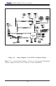
Quick Reference ( X6DAL-G/X6DAL-TG)